Connecng Detectors/Actuators to DX
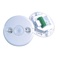
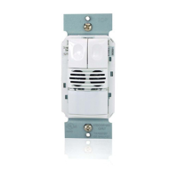
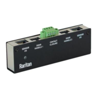
A DX sensor package comprises two parts: a sensor box and the terminal module(s). A terminal module
is removable.
Note: The following diagrams illustrate a terminal module comprising two terminaon points only. Your
DX terminal module may be larger if it has more terminals.
▶
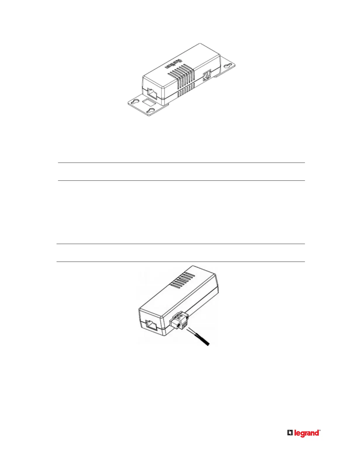
To make connecons when the terminal module is aached:
1) Strip the insulaon around 12 mm from the end of each wire of a detector or actuator.
• Wire size range: AWG 28 to 20 or 0.09 to 0.5 mm
2
•
2) Fully insert each wire into each terminaon point of a CC, DC or PDC channel on the DX sensor
package.
Important: For a PDC channel, you must check the electrical polarity markings (+ and -) on the DX label to
make sure each wire is inserted into the correct terminaon point with the correct polarity.
3) Use a screwdriver with a 2.5 mm wide sha to ghten the screws above each terminaon point to
secure the wires, using a torque of 0.196 N·m (2 kgf·cm).
50
 Loading...