MATRIX CONNECTION
The Matrix IP-PBX interfaces the Advent XT2 to the DECT equipment; it also gives access to an outside line
and allows zoning of calls.
24VDC - connect to the UPS via the in-line PSU module provided.
CO1 - connect to the Advent XT2 DECT 1 output using the RJ11/BT lead provided.
CO2 - connect to an external telephone line using the RJ11/BT lead provided.
CO3 - connect to the Advent XT2 DECT 2 output using the RJ11/BT lead provided.
SLT1 - connect to the CLI desk telephone via a BT master socket (cut plug off the RJ11/RJ11 lead provided).
ETHERNET - connect to the PoE injector using the RJ45 patch lead provided.
Note; in the event of a mains failure i.e. if the UPS batteries run flat or if a UPS is not fitted, the Matrix
connects CO1 to SLT1 and the Advent XT2 will only ring the CLI desk telephone.
IP-DECT SERVER 200 SINGLE CELL PROGRAMMING
The IP-DECT Server 200 must have its IP address set to 192.168.0.3 and its Radio Part Number set to 3.
Refer to the manufacturer’s installation guide for full instructions - see section 6.
4 CHANNEL MULTI CELL DECT REPEATERS
A maximum of six 4 Channel Multi Cell Repeaters can be used with the IP-DECT Server 200 Single Cell.
Repeaters require a power connection only; they communicate with the Server via low power radio signals
and do not require a line connection. To maintain DECT coverage during a mains failure all Repeaters must
be connected to a battery backed 12V DC PSU.
REPEATER POSITIONING
Before installing power cables to Repeater positions, it is important that the optimum position for coverage
is established. Register the Repeater onto the IP-DECT Server 200 then with the Repeater powered from a
battery walk away in the direction that cover is to be extended. When the red LED on the Repeater starts to
flash it is out of range and must be moved back towards the Server by a minimum of 5 metres before
selecting its final location. The LED should be steady green. See Repeater Deployment Rules on the
following page.
REPEATER PROGRAMMING
Refer to the manufacturer’s installation guide for full instructions – see section 6. A programming kit (P/No.
ZXT509) is required to program Repeaters, the Service Tool software can be downloaded via the link in
section 6 of this manual.
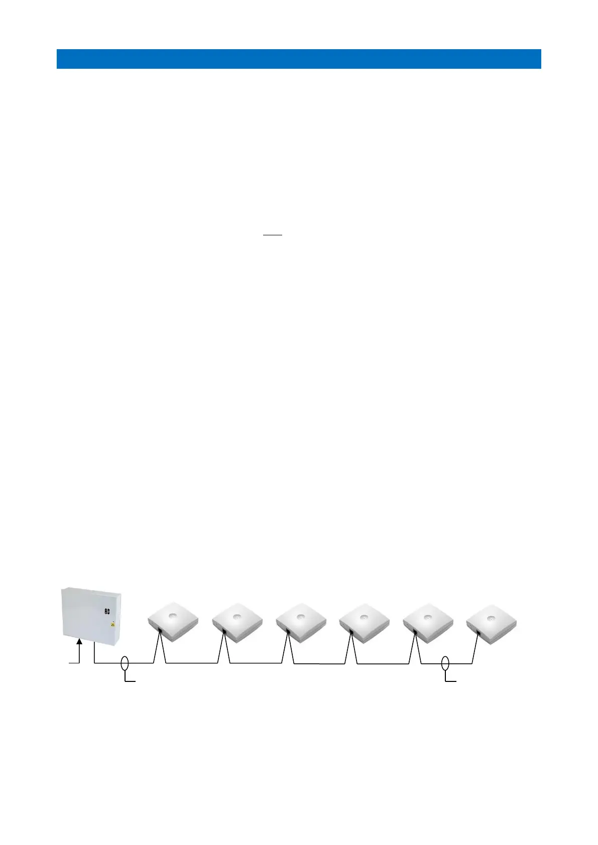
REPEATER POWER CONNECTION
Repeaters should be connected using 1.0 mm pair cabling, if CW1308 is being used then spare pairs can be
doubled-up and/or looped back to form a ring circuit to reduce the voltage drop if necessary.
 Loading...