6. DIAGRAMS AND TABLES
6.1 Lely Splendimo 240 MCR Diagrams and Schematics
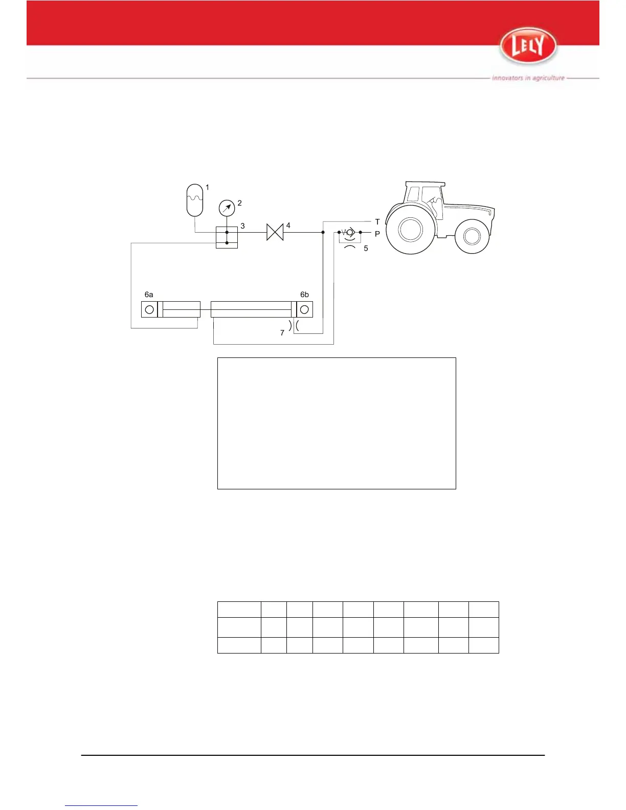
1. Accumulator
2. Pressure gauge
3. Connecting block
4. Ball valve
5. Throttle (1-way)
6. Combined ram
6a. Single-acting component (ground pressure relief)
6b. Double-acting component (lifting and lowering)
7. Throttle
Figure 35. Mechanically Controlled Hydraulic Schematic
6.2 Bolt and Nut Torque Table
The following table specifies the standard torque load for all quality 8.8 bolts
in combination with quality 8 nuts on the Splendimo.
Always
use a calibrated torque wrench when you torque-tighten bolts and nuts.
M6 M8 M10 M12 M14 M16 M20 M24
Nm 10 25 50 85 135 215 410 710
kgm 1.0 2.5 5.0 8.5 13.5 21.5 41.0 71.0
Diagrams and Tables 6-1
M-H025.1011EN