507343-01
Page 72
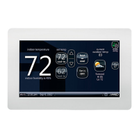
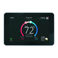
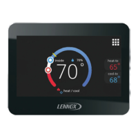
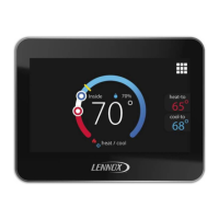
iComfort
®
INDOOR UNIT
OPTIONAL
DISCHARGE
AIR SENSOR
OPTIONAL OUTDOOR AIR
SENSOR
iComfort Wi-Fi
IN-ZONE
THERMOSTATS
PWR
D+
D-
C
PWR
D+
D-
C
PWR
D+
D-
C
(SEE IHARMONY
®
INSTALLATION
INSTRUCTION FOR CONNECTIONS
TO DAMPERS.
IHARMONY ZONING
SYSTEM
INDOOR
NOTE: USE TERMINAL DESIGNATED “IN
DOOR” ON DAMPER CONTROL TO CON
NECT TO THE INDOOR UNIT.
PWR
D+
D-
C
iComfort
®
OUTDOOR
UNIT
TSTAT
To indoor unit
To iHarmony
To thermostat
If unable to connect two
wires to indoor unit termi
nals then pigtail wiring is an
option.
Figure 14. iComfort Wi-Fi
®
, iHarmony
®
Damper Control Module, and Communicating Indoor Unit
DAS NOTE: The discharge air sensor is intended to be
mounted downstream of the heat exchanger and air
conditioning coil. It must be placed in free airflow, where other
accessories (such as humidifiers, UV lights, etc.) will not
interfere with its accuracy. Wiring distance between the IFC or
AHC and the discharge air sensor should not exceed 10 feet
when wired with 18-gauge thermostat wire.
OAS NOTE: The outdoor temperature sensor wiring distance
between the IFC or AHC should not exceed 200 feet when
wired with 18-gauge thermostat wire.
RSBUS NOTE Maximum total length of all connections on the
RSBus is limited to 1500 ft. (450 m). Max. length between
components is 300 ft. (90 m).
 Loading...
