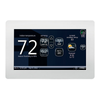
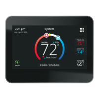
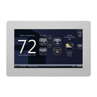
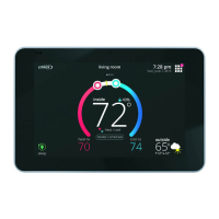
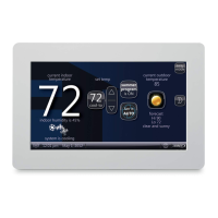
iComfort Wi-Fi
®
7-Day Programmable Communicating Thermostat
Page 73
FOR USE WITH ANY ICOMFORT
®
S30 CONTROL SYSTEM
SLP98 & G71MPP FURNACE
(IFC) OR AIR HANDLER (AHC)
DISCHARGE AIR SEN
SOR (REQUIRED FOR
EVEN HEAT) (SEE DAS
NOTE ON PAGE 81)
NOTE: iComfort Wi-Fi
®
SENSES HUMIDITY & CONTROLS 24V “H” OUTPUT (& 120V “H” OUTPUT) TO CYCLE HU
MIDIFIER BASED ON DEMAND. NO OTHER CONTROL OR HUMIDISTAT REQUIRED.
OPTIONAL OUTDOOR AIR SENSOR FOR USE WITH HUMIDIFIER (IF NOT ALREADY IN THE SYSTEM FOR OTHER
FUNCTIONS. BUILT INTO ALL iComfort OUTDOOR UNITS).
(SEE OAS NOTE ON PAGE 81)
Rf WGhGsCf
HVAC EQUIP
HCWH-01
DEHUMIDIFIER CONTROL
HVAC
EQUIPMENT
DH
NC
AUXILIARY DEHUMIDIFIER 090 & 135
capacities only (065 not compatible)
NOTE: 24V UV LIGHT
APPLICATIONS
In an iComfort
®
system, nei
ther furnace nor air handler
transformer will have ade
quate VA to power 24V UV
light applications. An addi
tional transformer for UV
light applications is required.
UV light wiring connections
are independent of HVAC
system operation; see UV
light installation instructions.
SL280, EL296 FURNACE
48G96 Relay
GND
IN
iComfort
®
outdoor unit
Smart Hub
RSBus
For SL290 & EL296, see HUMIDIFIER diagram
below (bottom right)
120VAC<-------HUMIDIFIER CONNECTIONS------> 24VAC
A
i+
B
-
A
i+
B
-
SMART HUB
HD
DISPLAY
Figure 15. Optional Accessories Wiring
FOR USE WITH ANY ICOMFORT
®
S30 CONTROL SYSTEM
RSBus
LVCS Ventilation Control System
iComfort
Furnace or Air Handler
HEPA Bypass Filter X2680 HEPA Interlock Kit
Pass indoor
blower motor
common wire
through cur
rent loop.
See HEPA In
terlock Kit for
installation
details
iComfort
Outdoor Air
Conditioning
or Heat Pump
Standard 1
or 2 stage
AC or HP
unit
iComfort
Furnace or
Air Handler
iComfort
Furnace or Air Handler
(POWER COMPANY INTERRUPTION
SYSTEMS ARE WIRED SAME AS
OVERFLOW SWITCH)
iComfort 2-STAGE
FURNACE
CUT
R-DS
W914
DS
R
26L56 Current sensing
relay kit.
NOTE: Pass the blower
motor L1 wire through the
current loop on the current
sensing relay as shown.
SLP98 & G71MPP FURNACE
(IFC) OR AIR HANDLER (AHC)
f
Vent
ODT
NOTE: Use the iComfort
®
circulate fan percentage of ON* TIME to control ventilation time.
LVCS. Set cycle time to 1 hour; set ventilation time to 60 minutes.
HVAC Heat or Cool call, or the fan is in continuous operation, the ventilation controller will open
OA damper to ventilate if the outdoor temperature and indoor humidity are within the limits of
the ventilation controller.
A
i+
B
-
A
i+
B
-
HD
DISPLAY
SMART HUB
Figure 16. Optional Accessories Wiring
 Loading...
