507343-01
Page 74
Thermostat Wire Termination in Communicating System
Indoor Unit
Controller
Outdoor Unit
IComfortiComfort
Wi-Fi
®
S30
Smart Hub
Single wire to
terminal C
Single wire to
terminal C
Unused wires
Unused wires
RSBus
Minimum wire size is 18
gauge
Maximum total length of all connections on the RSBus is limited to 1500 ft. (450 m). Max. length between components is 300 ft. (90 m).
Note: iComfort S30iComfort Wi-Fi
®
Controls do not require shielded
cable wiring.
BEST PRACTICES! Keep all communication wiring as far away from house electrical wiring and large electrical appliances as possible (15' [5m] re
commended).
Figure 17. Thermostat Wire Termination in Communicating System
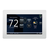
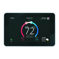
Communicating systems using the iComfort Wi-Fi
®
thermostat require four thermostat wires between the
thermostat and the furnace/air handler control and four wires
between the outdoor unit and the furnace/air handler control.
When a thermostat cable with more than four wires is used,
the extra wires must be properly connected to avoid electrical
noise. The wires must not be left disconnected.
Use wire nuts to bundle the unused wires at each end of the
cable. A single wire should then be connected to the indoor
unit end of the wire bundle and attached to the “C” terminals as
shown in the diagram above.
This is not an issue in non-communicating systems.
Configuring Heat Sections on Air Handler
Control
IMPORTANT: After electric heat strips are installed, the Air
Handler Control must be manually configured to detect the
number of electric heat sections. (See also 506181-01 for
complete configuration guide.)
This procedure is applicable only to the
CBX32MV-XX-230-6-06 and higher and CBX40UHV (all
models). To configure the heat strips so that they will be
detected by the thermostat:
Power must be applied to the air handler but NOT to the
thermostat. Remove thermostat from base plate or
remove wires to thermostat at the air handler.
On the air handler control, unit should be in idle mode
(decimal blinks at 1 Hertz—0.5 second ON, 0.5 second
OFF.
Select field test mode—press and hold the push button
until solid “–” appears; release button. Display will blink.
Press the push button and wait for the display LED to
show “H” (capital H), then release the button.
The air handler control cycles the indoor blower motor “on”
to the selected heat speed and stages the electric heat
relays “on” and “off” to automatically detect the number of
electric heat sections. The air handler control stores the
number of electric heat sections, then automatically exits
“Field Test Mode”.
At this point, the iComfort Wi-Fi
®
will now detect the heat
strip information stored in the air handler control.
OUTDOOR
AIR SENSOR
HEAT
1234
COOL
1234
DELAY
1234
ADJUST
NORM + −
HUMIDIFICATION
SMART
AUTO
EVENHEAT
1234
BLOWER
ONLY CFM
100
11 5
130
85
Y1−Y2
2−STAGE
COMPR
R−O
HEAT
PUMP
R−DS
DEHUM
OR
C
W1
W2
G
Y2
Y1
C
R
DH
H
L
O
DS
W3
FUSE 3 AMP
XFMR 24V
24 VAC
COM
3
6
9
1
4
7
XFMR LINE
G
2
5
8
P8
L1
L2
L2 L1
INDOOR
BLOWER
POWER
EARTH
INDOOR BLOWER
SIGNAL
4
5
6
12 3
A92
INTEGRATED
CONTROL
OUTDOOR UNIT
LINK
I + I −
I + I −RC
I + I −
R
C
THERMOSTAT
HUMIDITROL
DH
DISCHARGE
AIR SENSOR
HARMONY
PUSHBUTTON LED
 Loading...
