2. Main Controller Operation
Page 11
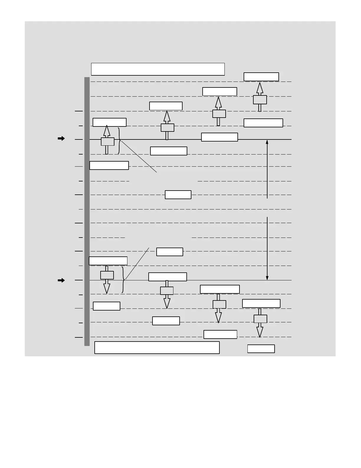
PRODIGYT M2 UNIT CONTROLLER
C2
ON
75°F
Default Oc-
cupied
Cooling
Setpoint
ECTO 6.04
−2.0°F
−1.5
°F
−0.5
°F
−1.0
°F
71
72
73
74
75
76
70
69
68
ON
OFF
OFF
Autochangeover Deadband
Must Be Greater Than ECTO 6.15
70°F
Default Oc-
cupied
Heating
Setpoint
ECTO 6.02
1°F
Cooling Stage Deadband
(All Stages Same Setting)
1°F
Heating Stage Deadband
(All Stages Same Setting)
ECTO 6.07
ON
OFF
ON
OFF
0.5°F Diff.
ECTO 6.10
1.0
°F Diff.
ECTO 6.12
1.5
°F Diff
ECTO 6.13
2.0
°F Diff
ECTO 6.14
ECTO 6.09
ECTO 6.11
ECTO 6.24
ECTO 6.25
ON
OFF
ON
OFF
ON
OFF
ON
OFF
−0.5
°F
ECTO 6.10 − 6.08
0.0
°F
ECTO 6.12−6.08
0.5
°F
ECTO 6.13−6.08
1.0
°F
ECTO 6.14 − 6.08
0.5
°F Diff.
ECTO 6.09 − 6.07
0.0
°F Diff.
ECTO 6.11 − 6.07
−0.5
°F Diff.
ECTO 6.24 − 6.07
−1.0
°F Diff.
ECTO 6.25 − 6.07
ECTO 6.08
Cooling stage−up timers 15 minutes. ECTO 4.20−4.22.
Cooling stage−down timers 15 minutes. ECTO 4.23.
Heating stage−up timers 15 minutes. ECTO 3.11.
Heating stage−down timers 0 minutes. ECTO 3.12.
C1=Cooling Stage 1
C2=Cooling Stage 2
C3=Cooling Stage 3
C4=Cooling Stage 4
Units With Economizer:
C1=Free Cooling
C2=Compressor 1
C3=Compressor 2
C4=Compressor 3 + 4
C1
C3
C4
H1
H2
H3
H4
H1=Heating Stage 1
H2=Heating Stage 2
H3=Heating Stage 3
H4=Heating Stage 4
Figure 3. Zone Sensor Stages For Gas / Electric Units (Default Values Shown)