9. Supply Air Delivery
Page 36
506457−01 05/10
9. Supply Air Delivery
9.1. Blower Delays
The following examples describe blower function for constant air volume (CAV) applications.
9.1.1. Gas / Electric Units:
The blower is delayed 40 seconds (default ECTO 3.02) after the gas valve is energized and 120 seconds (default ECTO
3.03) after the gas valve is de−energized. The blower operates anytime a heat limit trips.
9.1.2. Electric / Electric Units:
The default on delay is set to 0 (ECTO 2.02). The blower is delayed off for 20 seconds (default ECTO2.03) after the heating
demand is terminated.
9.1.3. Cooling Operation:
The default on and off delays are 0, but may be adjusted by ECTOs 4.02 or 4.03. The on−delay time period starts when the
cooling demand is initiated. The off−delay time period starts when the cooling demand is terminated.
9.1.4. Heat Pump Operation:
The default on−delay is 0 (ECTO 1.02),
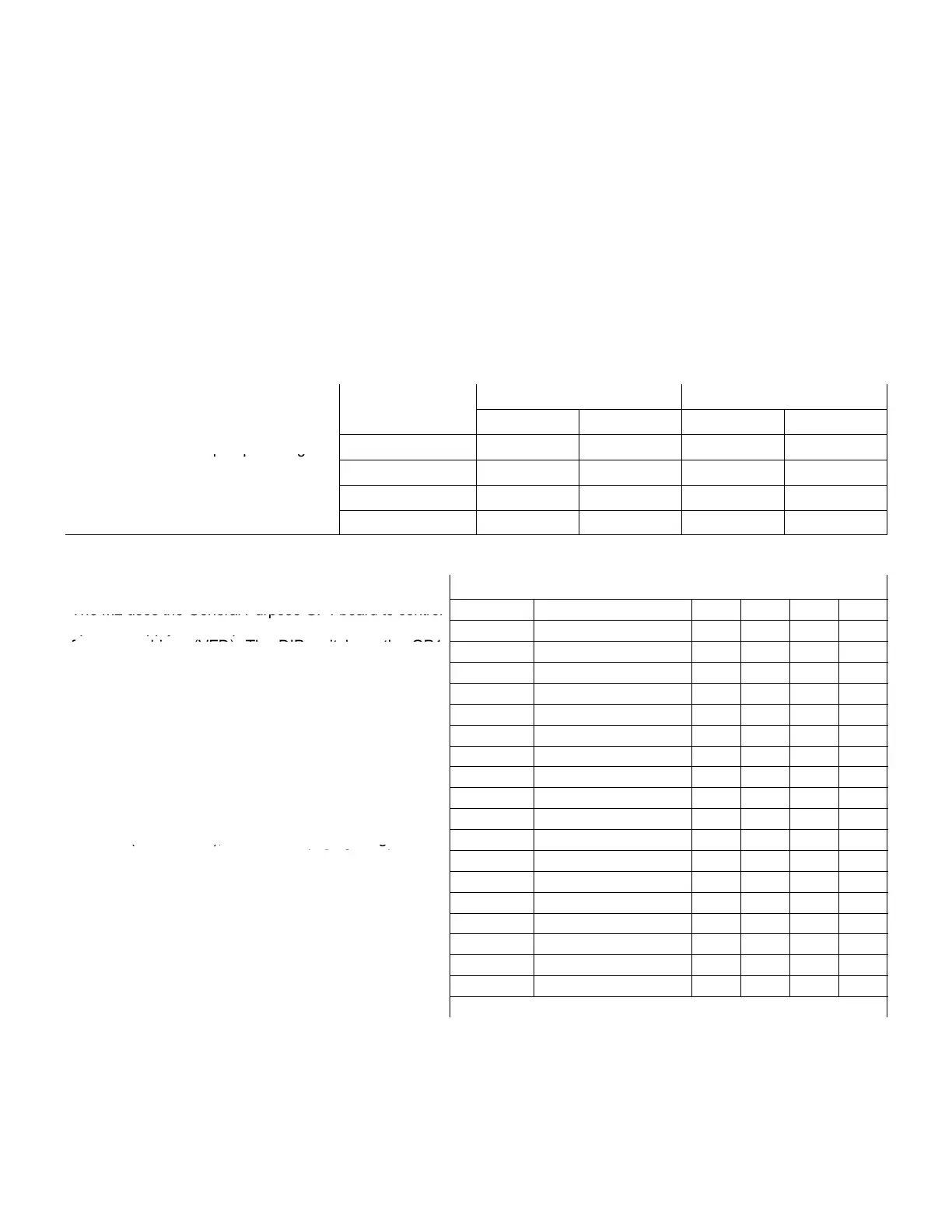
Blower On Delay Blower Off Delay
but the off−delay default is 20 seconds
−
Unit operation
Default ECTO Default ECTO
.
.
−
starts when the heat pump heating de-
Gas Heating 40 Sec. 3.02 120 Sec. 3.03
mand is initiated. The off−delay time pe-
riod starts when the heat pump heating
Electric Heating 0 Sec. 2.02 20 Sec. 2.03
r
o
s
ar
s w
en
e
ea
pump
ea
ng
demand is terminated. The followin
Cooling 0 Sec. 4.02 0 Sec. 4.03
.
chart summarizes blower delays.
HP Heating 0 Sec. 1.02 20 Sec. 1.03
9.2. Supply VAV Control Mode
Table 29. ECTO 0.01 Selection Summary
The M2 uses the General Purpose GP1 board to control
ECTO 0.01 Mode SMK VT CL HT
optional supply air and power exhaust blower variable
f d i (VFD) Th DIP it h th GP1
0 CAV − − − −
frequency drives (VFD). The DIP switch on the GP1
board must be set to VAV The GP1 controls the supply
1 CAV w/bypass damper PID PID PID PID
board must be set to VAV. The GP1 controls the supply
air VFD or by−pass damper in response to a duct static
3 VAV w/VFD (MSAV) STG STG STG STG
a
r
or
y−pass
amper
n response
o a
uc
s
a
c
pressure reading. VFD powered blowers can be varied
7 VAV w/VFD PID STG STG STG
.
or sta
ed.
11 VAV w/VFD STG PID STG STG
.
Th
P1
n
r in
n
VFD
r
−1
VD
.
15 VAV w/VFD PID PID STG STG
−
.
Duct static pressure sensor (A30) is 0
−
19 VAV w/VFD STG STG PID STG
−
.
.
The M2 has a maximum supply duct pressure limit
23 VAV w/VFD PID STG PID STG
ECTO 0.21
default 2w.c.
If this limit is exceeded the
27 VAV w/VFD STG PID PID STG
.
,
.
.
control will shut off the unit. After an off delay time of 5
31 VAV w/VFD PID PID PID STG
minutes (ECTO 5.02), the blower will re−energize. The
35 VAV w/VFD STG STG STG PID
control will lockout on the third trip (ECTO 0.22) and an
39 VAV w/VFD PID STG STG PID
M2 reset will be required.
Th f ll i l d ib i d li f ti
43 VAV w/VFD STG PID STG PID
The following examples describe air delivery for option-
al supply air VFD and by pass damper configurations
44 VAV w/VFD PID PID STG PID
al supply air VFD and by−pass damper configurations.
Refer to table 29 for a summary of ECTO 0 01 options
51 VAV w/VFD STG STG PID PID
e
er
o
a
e
or a summary o
.
op
ons.
55 VAV w/VFD PID STG PID PID
59 VAV w/VFD STG PID PID PID
63 VAV w/VFD PID PID PID PID
STG=Staged Control; PID=PID Loop or Modulating Control
9.2.1. Local Thermostat Mode, Single Zone CAV Units
ECTO 6.01 option 0 (Default)
This configuration is used for thermostat or DDC applications when the blower is controlled by the G thermostat demand
24VAC input.