4. Sensors
Page 15
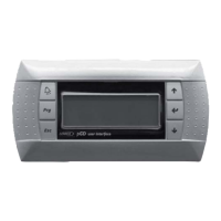
PRODIGYT M2 UNIT CONTROLLER
3.10.2. Safety Switch Input (A42−Optional)
The M2 has a 24 volt optional input (DI−3) which may be used for additional safety switches (such as a blower overload, loss
of phase protector, or supply duct high pressure limit switch). Wire the safety switch in series with the input. When the input is
de−energized, the M2 will turn off all outputs and display error code #20 (ECTO 5.08). For normal operation, the input must
be energized with 24VAC.
Table 7. Smoke Alarm Operation
ECTO
Exhaust Fan
Fresh Air
5.01
Blower
Single/Two Stage (2) VFD
Damper
Description
0 Off Off Off Closed Unit Off
1 On (1) Off Off Open Positive Pressure
2 On (1) On Speed = ECTO 8.19 Closed
Negative Pressure w/ Blower
Exhaust fan at fixed speed
3 On (1) On Speed = ECTO 8.19 Open
Purge
Exhaust fan at fixed speed
4 Off On Speed = ECTO 8.19 Closed
Negative Pressure
Exhaust fan at fixed speed
5 On (1) On Building Static SP=ECTO 8.19 Closed
Negative Pressure w/ Blower
Exhaust fan modulates
6 On (1) On Building Static SP=ECTO 8.19 Open
Purge
Exhaust fan modulates
7 Off On Building Static SP=ECTO 8.19 Closed
Negative Pressure
Exhaust fan modulates
(1)−Blower with VFDs operation depends on ECTO 0.01 settings. If set to PID, supply static SP = ECTO 0.02, if set to staged, blower
speed = ECTO 0.02. For CAV units with bypass dampers, supply static SP= ECTO 0.13.
(2)−Both exhaust fan stages will operate on units with two stage fans.
4. Sensors
The M2 is only compatible with L connections sensors provided with the unit or purchased separately as specified in the
Engineering Handbook.
IMPORTANT − All 0−10Vdc sensors require two separate twisted pair cables with shield. one cable is used for the 24Vac
power and one cable is used for the 0−10Vdc output. Zone sensors require a single twisted pair cable with shield. The shield
drain wires must be connected to the common at the unit field wiring terminal block only. The shield drain wires must not be
connected to common at the sensor.
4.1. Temperature Sensors − Provided With Unit
The return air (RT16) and discharge air (RT6) duct probes and the outdoor air (RT17) are all two wire thermistors. The resist-
ance vs. temperature table is shown below:
Temp. °F (°C) Resistance +/−2% Temp. °F (°C) Resistance +/−2% Temp. °F (°C) Resistance +/−2%
−40 (−40.0) 335,671 40 (4.4) 26,106 90 (32.2) 7,332
−20 (−28.9) 164,959 50 (10.0) 19,904 100 (37.8) 5,826
0 (−17.8) 85,323 60 (15.6) 15,313 120 (48.9) 3,756
20 (−6.7) 46,218 70 (21.1) 11,884 130 (54.4) 3,047
30 (−1.1) 34,566 80 (26.7) 9,298
4.2. Optional Zone Sensor
Zone sensors (A2) are two wire thermistor with 1k series resistor.
Temp. °F (°C) Resistance +/−2% Temp. °F (°C) Resistance +/−2% Temp. °F (°C) Resistance +/−2%
40 (4.4) 27,102 60 (15.6) 16,313 80 (26.7) 10,299
45 (7.2) 23,764 65 (18.3) 14,474 85 (29.4) 9,249
50 (10.0) 20,898 70 (21.1) 12,882 90 (32.2) 7,529
55 (12.8) 18,433 75 (23.9) 11,498
4.3. Optional Relative Humidity Sensor
The indoor Rh sensor (A91) is an analog sensor with a 0−10 Vdc output over an Rh range of 0−100%rh. The sensor is pow-
ered with 24Vac.