1. Prodigy M2 Unit Controller Description
Page 6
506457−01 05/10
1. Prodigy M2 Unit Controller Description
The M2 Unit Controller provides all rooftop unit control functions to insure its safe and reliable operation. It also provides
status and diagnostic information to facilitate troubleshooting. The controller’s programmable parameters allow adjustment
of time delays and setpoints that enable advanced features.
The default configuration requires a standard room thermostat or direct digital controller (DDC). By changing a single pa-
rameter, the M2 can also control the unit from a zone sensor. The M2 Unit Controller can also be configured as a network
controller when daisy−chained to the L Connection® Network. To simplify configuration, the M2 may be connected to a PC
which has been loaded with Unit Controller software.
1.1. Add−on boards
Add−on boards connect to the main board to build variations according to application or equipment type.
Packaged Unit A55 A59 A169 A133 VAV A133 MGV A133 GP
Models
Box
Size
M2 Unit
Controller
C2, #3 & 4 Com-
pressor Board
MCB1 Motor
Control Board
GP1 Variably Air
Volume Board
GP1 Modulating
Gas Valve Board
GP1 General Pur-
pose I/O Board
LCH/LGH 036−060 S A X X O* O
LCH/LGH 036−060 H A X X O
LCH/LGH 072 H A+ X O* O
LCH/LGH 092−150 H/S B X O* O
LCH/LGH 156 H C X X O* O
LCH/LGH 180 H C X X O* O
LCH/LGH 210 H C X X O* O
LCH/LGH 240/300 S C X X O* O
LCH/LGH 420−600 H/S E X X O O O
X = required; O = optional: * only CAV Bypass supported, no VFD drives.
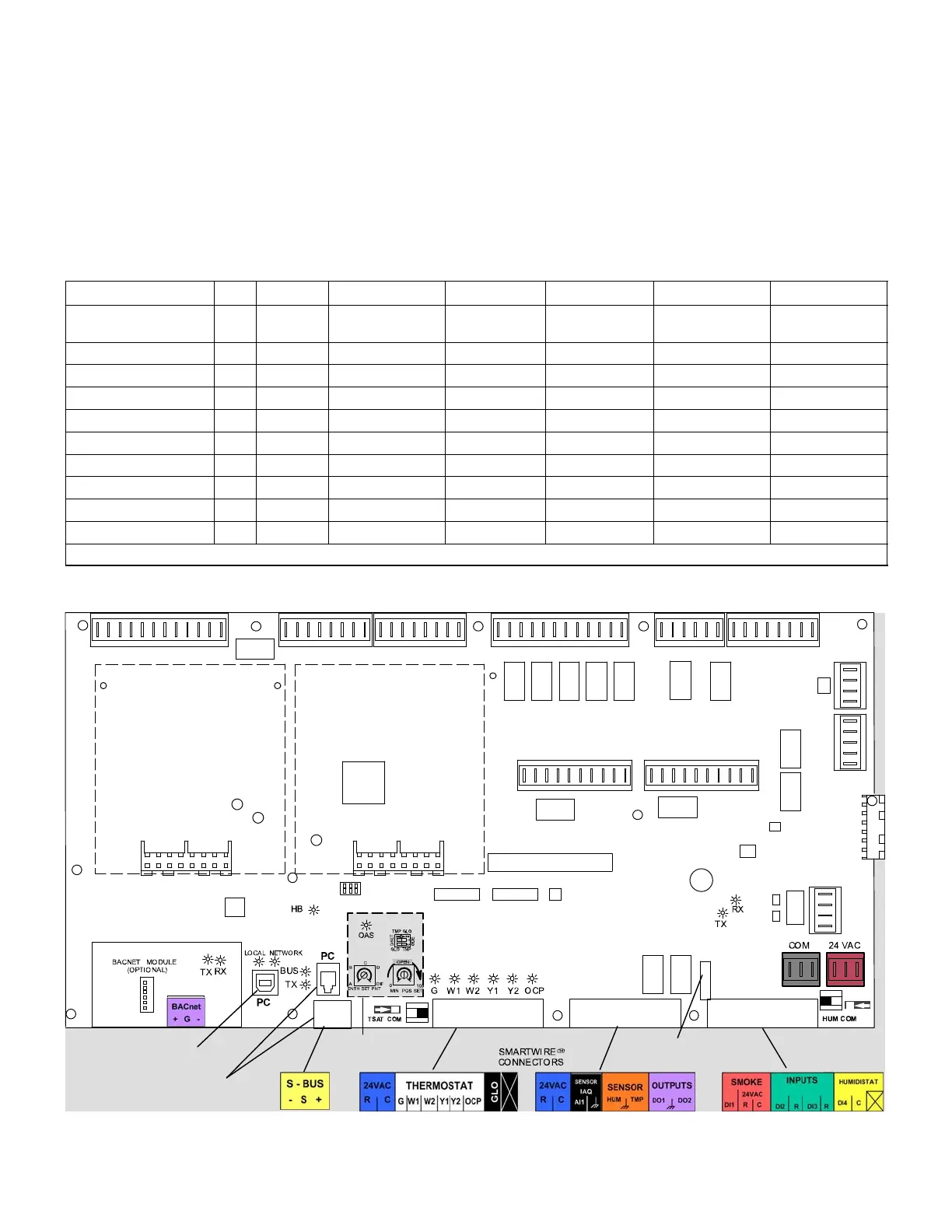
Figure 1 shows the M2 integrated modular controller components and the location of the add−on boards.
EXPANSION
PORT
ECONOMIZER POTS
AND DIP SWITCHES
EXPANSION
PORT
2 AMP FUSE
CONTROL
BOARD
CONTROL
BOARD
L CONNECTION ( optional
connection method for Unit
Controller software)
USB CONNECTION
(for Unit Controller
software)
Figure 1. M2 Unit Controller and Expansion Board Locations