2. Main Controller Operation
Page 8
506457−01 05/10
Table 4. Default Thermostat Mode Operation (Electric Heat)
No. of Heat Sections Stages Per Section W1 Demand W2 Demand
1 1 Stage 1 Stage 1
1 2 Stage 1 Stage 2
2 1 High Rate − Both Sections High Rate − Both Sections
2 2 Low Rate − Both Sections High Rate − Both Sections
Table 5. Thermostat Mode Operation (Heat Pump Heat)
Unit Type W1 Demand W2 Demand Adds
1 Compressor / 1 Stage Electric Heat CP1 Heating Electric Heat
2 Compressors / 1 Stage Electric Heat CP1 + CP2 Heating Electric Heat
2.2. System Mode − Zone Sensor
ECTO 6.01 option 1, 2, or 3 allows the M2 Unit Controller to use internal setpoints and input from a zone sensor to operate
the unit. An additional thermostat or Energy Management System is not required.
Internal setpoints can be adjusted using the Select button and Arrows on the M2 Unit Controller. Refer to the Electronic
Configure To Order (ECTO) section in this manual. In zone sensor mode, during the occupied time period, the default M2
internal heating and cooling setpoints are:
Cooling setpoint: 74°F (ECTO 6.04)
Heating setpoint: 70°F (ECTO 6.02)
Use ECTO stage differential and deadband options to adjust setpoints in zone sensor mode.
2.2.1. Network Control Panel (NCP)
The setpoints can also be adjusted using the optional NCP Network Control Panel. When an NCP is installed, the setpoints
are determined by the NCP schedule. The NCP communicates with the M2 via the L Connection network bus. Internal M2
setpoints are used only if network communication is interrupted.
The zone sensor is wired directly to each unit P298−6 and P298 −7 (marked GND and TMP on the Field Wiring Termination
Plugs). The zone sensor wiring diagram key number is A2.
2.2.2. Zone Sensor Back−Up Modes
Select the appropriate ECTO 6.01 option to determine the zone sensor back−up mode. The back−up mode is used in the
event that the A2 room sensor fails or is disconnected.
S Option 1−M2 Zone Sensor System Mode 1 has no back−up mode of control should the A2 zone sensor fail.
S Option 2−M2 Zone Sensor System Mode 2 will default to a local thermostat if one is installed (should the A2 zone sensor
fail). The M2 will switch over and operate based on the signals from the room thermostat.
S Option 3−M2 Zone Sensor System Mode 3 will default to return air sensor RT16 (should the A2 zone sensor fail). The
M2 will switch over and operate based on the temperature from the return air sensor. RT16 is standard on all units;
therefore M2 Zone Sensor System Mode 3 is the recommended System Mode when units are setup in the zone sensor
mode.
NOTE − The RT16 has a lower resolution than the A2 zone sensor and should only be used as back−up.
2.2.3. L Connection Network Back−Up Setpoints
ECTO 6.02 through 6.05 back−up setpoints are used when the communication link has been lost on the L Connection sys-
tem bus. Five minutes after communication is interrupted, the M2 will reset and start using the back−up setpoints. The M2 will
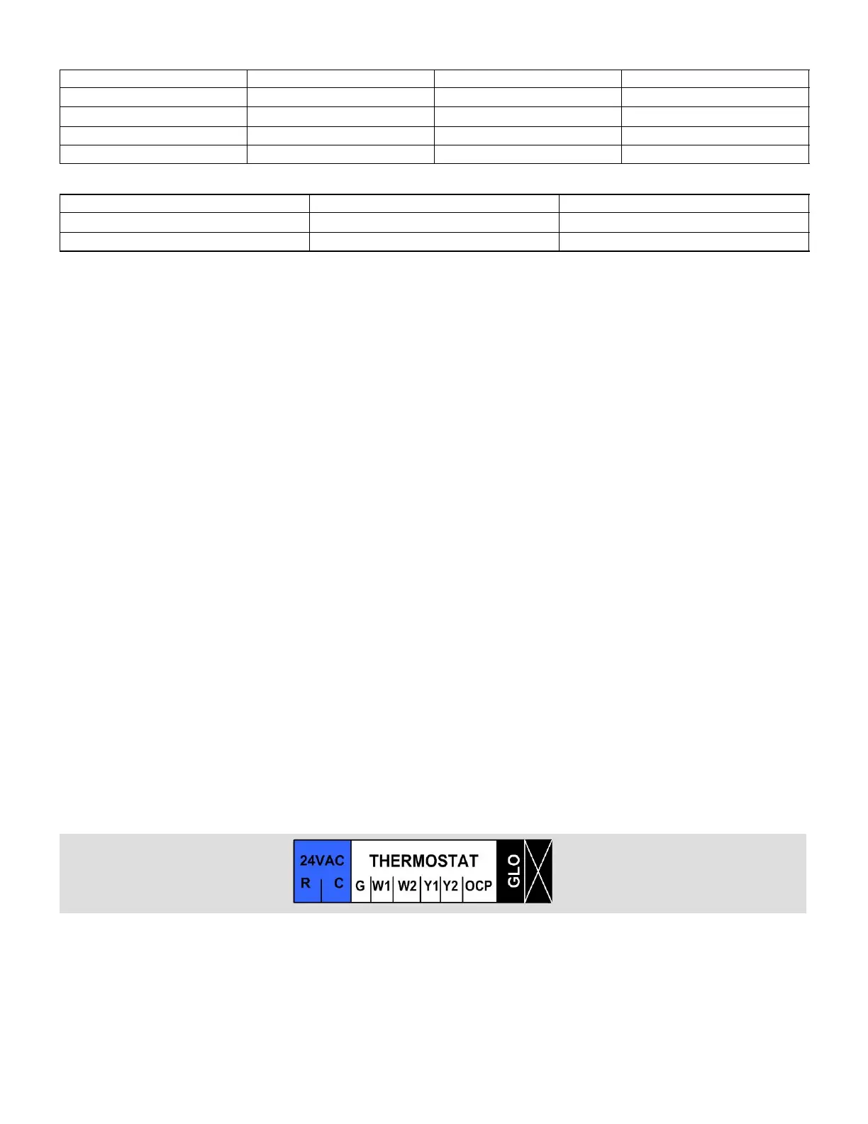
default to occupied (6.02 & 6.04) back−up setpoints when the factory−installed jumper between P297−1 and P297−8 (marked
R" and OCP" on the P297 label) is left in place.
It is recommended that occupied back−up setpoints be used. If the unoccupied (6.03 & 6.05) back−up setpoints are desired,
remove the factory−installed jumper between P297−1 and P297−8.
During normal zone sensor operation with an NCP, the occupied demands are sent over the network and the occupied input
on P297−8 is ignored. The occupied input on P297−8 is only read if the network communication link is lost.
2.2.4. Heating & Cooling Stages in Zone Sensor Mode
In Zone Sensor Mode, default operation, the M2 controls up to 4 stages of heating and 4 stages of cooling. See figure 3 and
ECTO parameters in table 6.