2. Main Controller Operation
Page 7
PRODIGYT M2 UNIT CONTROLLER
2. Main Controller Operation
2.1. System Mode − Thermostat
The M2 will operate the unit from a thermostat, zone sensor, or the zoning system based on the System Mode selected in
ECTO 6.01. The default System Mode (option 0) is the thermostat mode.
DDC applications use thermostat mode for two or three−stage cooling and two−stage heating.
Units are shipped from the factory in system mode 0, Thermostat Mode. The M2 will operate two stages of heating and
cooling based on the thermostat Y1, Y2, W1, W2, G, and OCP (occupied) demands.
2.1.1. Cooling Stages
The M2 allows three different staging options; adjust ECTO 5.04 to select the option.
S Option 1. Two Cooling Stages: Y2 demand brings on all mechanical stages of cooling during economizer operation.
S Option 2. (Default) Two Cooling Stages: Cooling operation is shown in table 1. Y2 demand brings 1/2 or 2/3 mechani-
cal stages of cooling during economizer operation.
S Option 3. Three Cooling Stages: Cooling operation is shown in table 2; this option requires the use of a three−stage
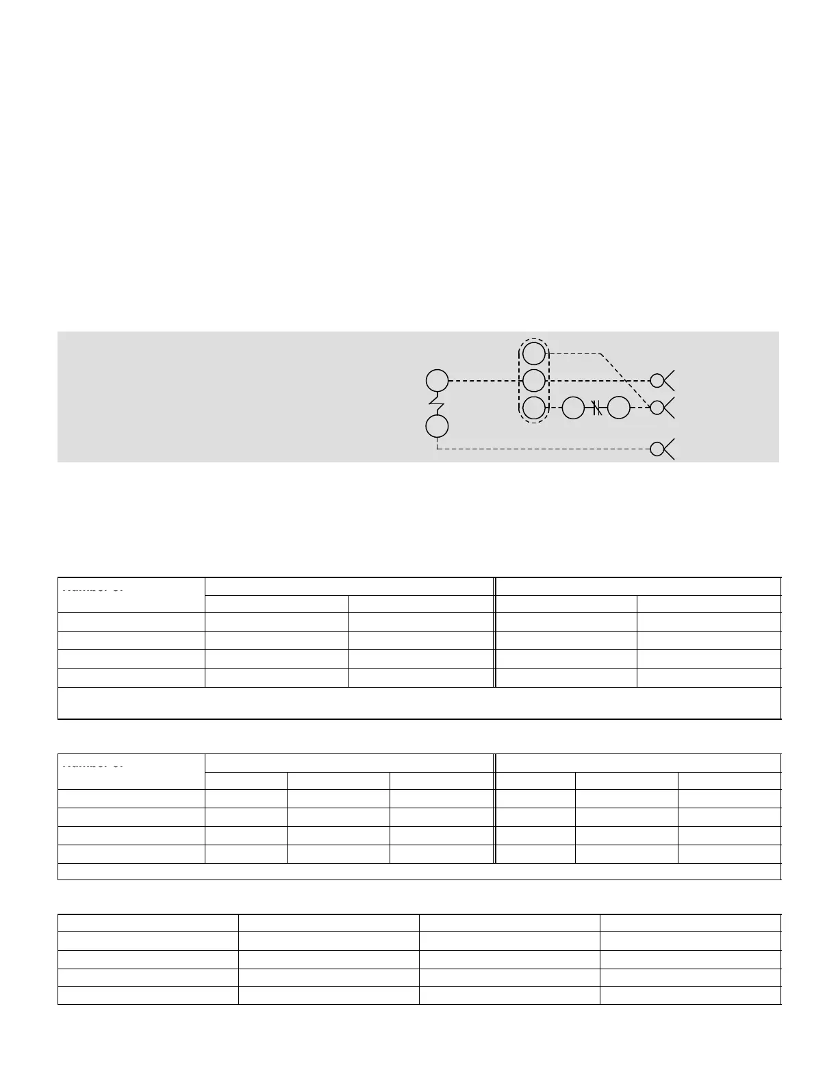
cool thermostat and a K27 relay. See wiring pictorial in figure 2 and wiring diagram control C section.
TO PROVIDE THREE COMPRESSOR STAGES.
REQUIRES 3 HEAT, 3 COOL THERMOSTAT AND K27 RELAY.
K27
A
B
A2
Y1
Y2
Y3
K27−1
17
J297A
7
6
2
Figure 2. 3−stage cool (ECTO 5.04 opt. 3) wiring
2.1.2. Heating Stages
The M2 default thermostat operation is for two heating stages. See table 3 for gas heat units, table 4 for electric heat units,
and table 5 for heat pump units.
Table 1. Thermostat Mode Operation Default (Two Cooling Stages ECTO 5.04 Option 2)
Number of
No Economizer With Economizer
Compressors
Y1 Demand Y2 Demand Adds Y1 Demand Y2 Demand Adds
1 CP1 CP1 Free Cool CP1
2 CP1 CP2 Free Cool CP1
(1)
3 CP1 + CP2 CP3 Free Cool CP1 + CP2
(1)
4 CP1 + CP2 CP3 + CP4 Free Cool CP1 + CP2
(1)
CP1 = Compressor 1, CP2 = Compressor 2, CP3 = Compressor 3, CP4 = Compressor 4.
(1)
− ECTO 5.04 option 1 will bring on all available mechanical cooling. *Assumes outdoor air is suitable for cooling.
Table 2. Thermostat Mode Operation (Three Cooling Stages ECTO 5.04 Option 3)
Number of
No Economizer With Economizer
Compressors
Y1 Demand Y2 Demand Adds Y3 Demand Adds Y1 Demand Y2 Demand Adds Y3 Demand Adds
1 CP1 CP1 CP1 Free Cool CP1 CP1
2 CP1 CP2 CP2 Free Cool CP1 CP2
3 CP1 CP2 CP3 Free Cool CP1 CP2
4 CP1 + CP2 CP3 CP4 Free Cool CP1 + CP2 CP3
CP1 = Compressor 1, CP2 = Compressor 2, CP3 = Compressor 3, CP4 = Compressor 4. *Assumes outdoor air is suitable for cooling.
Table 3. Default Thermostat Mode Operation (Gas Heat)
No. of Heat Sections Gas Valve W1 Demand W2 Demand
1 (1) 1 Stage Gas Valve 1 Gas Valve 1
1 (1) 2 Stage Low Rate High Rate
2 (2) 1 Stage High Rate − Both Valves High Rate − Both Valves
2 (2) 2 Stage Low Rate − Both Valves High Rate − Both Valves