11. Third−Party Zoning
Page 48
506457−01 05/10
11. Third−Party Zoning
The M2 has many features which allow easy interface with third−party VAV or bypass damper changeover zoning systems.
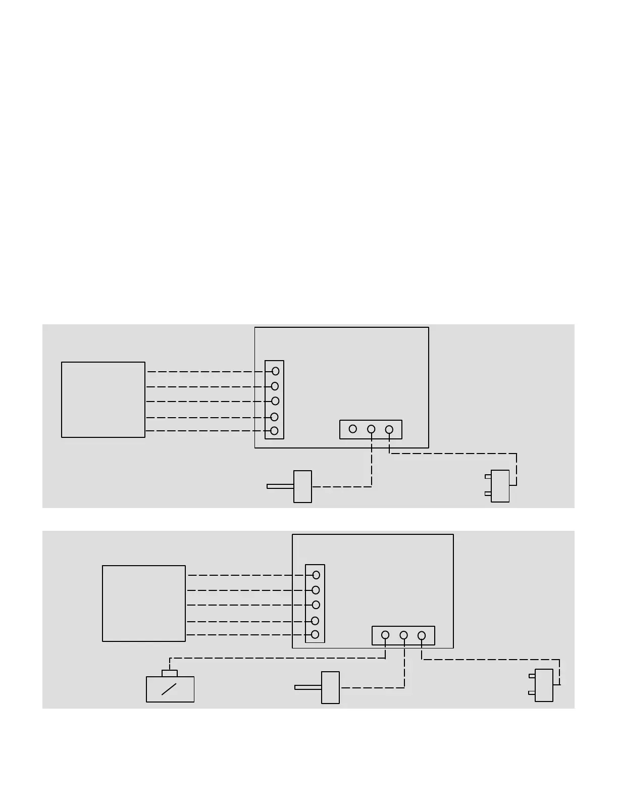
See Figure 26 for a VAV unit wiring summary and figure 27 for a CAV unit w/CAVB wiring summary.
In addition to providing VFD control (VAV units) and bypass damper control (CAV units), the M2 provides discharge air con-
trol for cooling and/or heating. More options are available which control single-stage, two-stage, or modulating power ex-
haust fans.
Only 4 digital inputs are required to control the rooftop unit for third−party zoning applications: G (blower enable), OCP (occu-
pied), Y1 (enables discharge cooling) and W1 (enables discharge heating).
11.1. Air Delivery Operation
When a G signal is energized, the M2 will control a VFD or bypass damper to hold a constant supply duct static pressure. The
M2 uses a pressure sensor input and a PID control loop to maintain duct static pressure. For increased flexibility, the M2 has
separate adjustable static pressure setpoints for ventilation, cooling, heating and smoke alarms.
11.2. Occupied /Unoccupied Operation
When the OCP signal is energized, the M2 will adjust the fresh air damper to a fixed minimum position or a modulating
position (based on a CO
2
or outdoor air control sensor). Also during morning warm−up/cool−down the M2 will keep the damp-
er closed based on the settings selected.
11.3. Cooling Operation
When a Y1 signal is energized the M2 will control up to 4 stages of cooling (depending RTU size) to automatically maintain a
constant discharge air cooling temperature. The M2 also has advanced discharge air cooling reset options based on return
air temperature and/or outside air temperature.
RTU w/M2
TB18
Heating Demand
Cooling Demand
Occupied Demand
Ventilation Demand
3
rd
Party Zoning
Control System
24VAC Digital Signals
Common
G
OCP
Y1
W1
C
Supply Static Pr.
Sensor (A30)
Optional Building Static
Pressure Switch(s)
(S37,S39) or Sensor (A34)
Figure 26. Field Wiring Summary for VAV Unit with Supply Air VFD
Heating Demand
Cooling Demand
Occupied Demand
Ventilation Demand
RTU w/M2
3
rd
Party Zoning
Control System
TB18
24VAC Digital Signals
Common
G
OCP
Y1
W1
C
Bypass Damper
2−10V, 2V Full Open
Optional Building Static
Pressure Switch(s)
(S37,S39) or Sensor (A34)
Supply Static Pr.
Sensor (A30)
Figure 27. Field Wiring Summary for CAV Unit with Bypass Damper