11. Third−Party Zoning
Page 49
PRODIGYT M2 UNIT CONTROLLER
11.4. DACC Outdoor Air Reset
The outside air reset saves energy by gradually increasing the discharge air setpoint as the outside air temperature de-
creases.
11.5. DACC Return Air Reset
The return air reset reduces the possibility of overcooling by gradually increasing the discharge air setpoint as the return air
temperature decreases. Overcooling may occur if the zoning system is misapplied, has an abnormal condition, or a domi-
nant zone.
11.6. Heating Operation
When a W1 signal is energized, the M2 will control up to 4 stages of heating (depending on RTU size) to automatically main-
tain a constant discharge air heating temperature. The M2 also has advanced discharge air heating reset options based on
return air temperature and/or outside air temperature.
11.7. DACH Outdoor Air Reset
The outside air reset saves energy by gradually decreasing the discharge air setpoint as the outside air temperature in-
creases.
11.8. DACH Return Air Reset
The return air reset reduces the possibility of overheating by gradually decreasing the discharge air setpoint as the return air
temperature increases. Overheating may occur if the zoning system is miss−applied, has an abnormal condition, or domi-
nant zone.
11.9. Power Exhaust Operation
The M2 has many power exhaust fan control options that include single-stage, two-stage and modulating control depending
on how the unit is equipped. The stage control options can be triggered based on fresh air damper position, pressure
switches or pressure analog sensor. The modulating control for units with VFD powered exhaust fans are typically modu-
lated to maintain building static pressure, but can also be staged. See Power Exhaust Section.
11.10. VAV and CAVB Analog Outputs
Refer to the Supply Air Delivery section and the optional Power Exhaust Fan section.
11.10.1. VFD Control
The M2 is only compatible with the factory−installed variable frequency drives (VFD) provided in VAV units. The VFD is used
to control the supply blower and exhaust fan(s). The analog control for the VFDs is 0−10Vdc. This manual uses percent (%)
to indicate blower and fan speeds. For example, 50% blower speed is equal to 30Hz and 5Vdc.
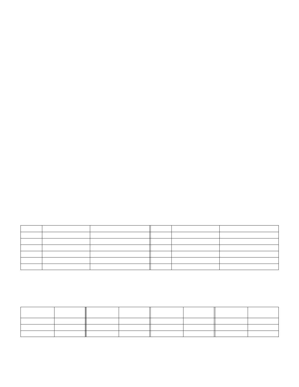
Speed % Motor Frequency (Hz) VFD Control Voltage (VDC) Speed % Motor Frequency (Hz) VFD Control Voltage (VDC)
0 0 0 60 36 6
10 6 1 70 42 7
20 12 2 80 48 8
30 18 3 90 54 9
40 24 4 100 60 10
50 30 5
11.10.2. Supply Bypass Damper Control
The M2 is only compatible with bypass damper actuators specified in the Engineering Handbook. The actuators control the
supply air volume for constant air volume units equipped with a bypass damper (CAVB) in zoning applications. The analog
control for the actuator is 2−10Vdc. Dampers are closed at 10Vdc and fully open at 2Vdc. This manual uses percent (%) to
indicate bypass damper position. For example, 70% bypass damper position is equal to 4.4Vdc.
Bypass Damper
Position (%)
Control
Voltage (VDC)
Bypass Damper
Position (%)
Control
Voltage (VDC)
Bypass Damper
Position (%)
Control
Voltage (VDC)
Bypass Damper
Position (%)
Control
Voltage (VDC)
0 (closed) 10 30 7.6 60 5.2 90 2.8
10 9.2 40 6.8 70 4.4 100 2.0
20 8.4 50 6.0 80 3.6