7. Economizer
Page 31
PRODIGYT M2 UNIT CONTROLLER
Min. Position
100
ECTO 5.16
ECTO 5.18 (full) ECTO 5.17 (start)
CO
2
(ppm)
Max. Open
Close Open
Figure 15. Setpoint Control IAQ Option
7.12.3.2. Determine IAQ Input
Check IAQ input (ppm) by using the "DATA/SENSORS" menu selection from the Prodigy display.
7.12.4. Outdoor Air Control Sensor (OAC)
An optional flow sensor (A24) may be used to control the amount of outdoor air brought into the space. If option 2 for
ECTO 5.26 is selected, the M2 will modulate the outdoor air damper in order to hold a constant outdoor airflow. This
option is very useful in VAV applications to maintain a constant outdoor airflow as the delivered air volume varies. A
0−10VDC flow meter located in the unit fresh air intake provides a signal to the general purpose board input
A133_P194−6 (TB22−6). The M2 will modulate the damper based on ECTO 5.16 through 5.22 and ECTO 9.09−9.11 in
order to maintain a constant air flow..
Unless the OAC kit instructs otherwise, use
ECTO 5.17 = 0
ECTO 5.18 = 255
ECTO 5.26 = 2 (use 3 for no OAT limits)
ECTO 9.01 = 5
ECTO 9.09 = 2
ECTO 9.10 = 30
Adjust ECTO 5.19 through 5.22 to modify Outdoor Air Flow operation based on the outdoor air temperature. Select
ECTO 5.26 option 3 when this option is not desired.
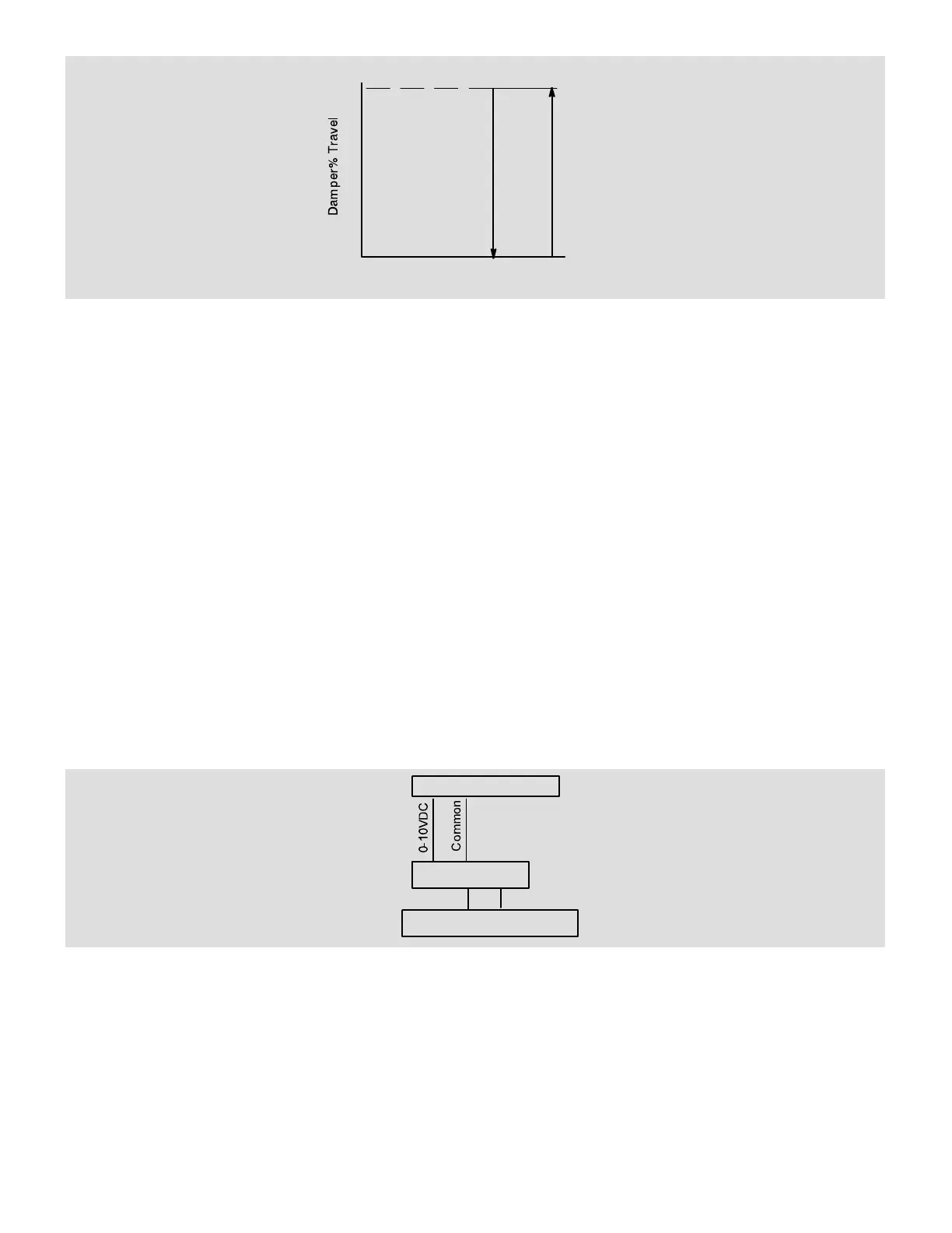
In OAC mode, the M2 closes the damper as voltage increases to maintain a constant amount of fresh air. The sensor will
read 10VDC at maximum flow and 0VDC at minimum flow.
7.12.4.1. Field Wiring
When outdoor air control sensor is field−installed, connect as shown in figure 16.
Velocity Sensor A24
TB22
IAQ+
10 116
IAQ−
PRODIGY
IAQ PLUG
Figure 16. OAC Sensor Wiring
7.12.4.2. Set Damper Minimum Position
1. Operate unit at full supply air CFM with all zone dampers open. Refer to VFD Supply Air Blower Start−Up section in
the unit installation instruction.
2. Use an air flow hood to measure the outdoor air CFM entering the unit.
3. Set economizer DIP switch to DSET" position as shown in figure 17. DIP switch is located in the economizer section.
4. Adjust the MIN POS SET potentiometer until the air flow hood reads the design minimum outdoor air CFM (see figure
17.)
NOTE − Refer to local codes or authorities having jurisdiction when determining design minimum outdoor air require-
ments.