8. Power Exhaust Operation
Page 34
506457−01 05/10
8. Power Exhaust Operation
8.1. Single Fan or Blower
The M2 has several exhaust control options selected by ECTO 8.16. The default operation, option 0, is single−stage ener-
gized when the fresh air damper opens to 50% Travel (ECTO 8.20). The blower must be operating.
Units equipped with an A133 (GP) board with the DIP configuration switch set to VAV, may control the fan by a building
pressure switch (S37 or S39) or a pressure transducer (A34).
8.2. Two Fans or Blowers
Units equipped with two−stage exhaust fan and A133 (GP) board with the DIP configuration switch set to VAV, may control
the fan stage by two fresh air damper position setpoints, two pressure switches or from two pressure sensor setpoints.
8.3. Exhaust Blower VFD
Units equipped with a power exhaust VFD and A133 (GP) board with the DIP configuration switch set to VAV, may vary the
speed of the blower to maintain a building pressure setpoint.
There are four exhaust fan enable options to choose from when the unit is equipped with a GP board:
1. On when blower is energized.
2. On always.
3. On during occupied period.
4. On if optional digital input A133_P194_1 is energized.
See table 28 for more details.
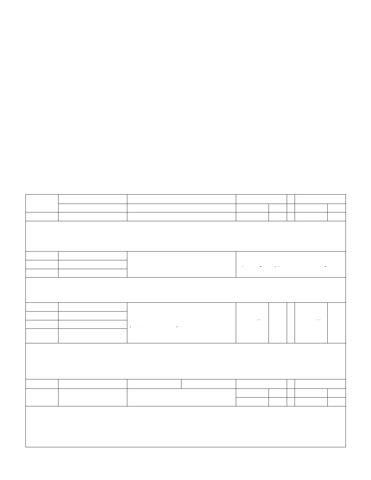
Table 28. ECTO 8.16 Exhaust Control
Option
Single−Stage Exhaust
Setpoints Deadband
ECTO 8.16
Enabled when Input Default ECTO Default ECTO
0 Blower is energized. Fresh Air Damper Position 50% Travel 8.20 10% Travel 8.21
CAV units with single stage exhaust fans use the A55_P265−11 output to energize the exhaust relay when the fresh air damper position reaches
50% Travel (ECTO 8.20) when the blower is operating. The exhaust will de−energize when the damper position decreases 10% (ECTO 8.21)
less than the setpoint or when the blower is de−energized.
VAV units with VFDs could use this option for single stage operation. In that case, the A55_P265−11 output is used to enable the VFD and the
exhaust fan will operate at speed set with ECTO 8.17 (50% default).
1 Always
A133 Di it l I t 1 (P194 1)(TB18 1)
2 Occupied
A133 Digital Input 1 (P194−1)(TB18−1)
Pressure Switch S37
Input energized by pressure switch setting.
3 Blower is energized.
On units equipped with an A133 board set for VAV operation, the exhaust fan will be energized when enabled and the Digital Input 1 is energized. This
option typically would have a building pressure switch connected to the Digital Input.
VAV units with VFDs could use this option for single stage operation. In that case, the A55_P265−11 output is used to enable the VFD and the ex-
haust fan will operate at speed set with ECTO 8.17 (50% default).
4 Always
5 Occupied
A133 Analog Input 2 (P194−7) (TB18−7)
6 Blower is energized
na
og
npu
−
−
(Pressure Sensor A34)
−0.3"w.c.
(1)
8.20 0.04"w.c.
(1)
8.21
7
A133 Digital Input 1 (P194−1)
is energized (enable switch)
(1)
Settings require adjustment in most cases.
CAV units equipped with an A133 board set for VAV operation, the power exhaust will be energized when enabled and the Analog Input voltage is at or
above ECTO 8.20 setting. Exhaust air will de−energize when the voltage decreases by the deadband set with ECTO 8.21. This option typically would
have a building pressure sensor connected to the Analog Input.
VAV units with VFDs could use this option for single stage operation. In that case, the A55_P265−11 output is used to enable the VFD and the ex-
haust fan will operate at speed set with ECTO 8.17 (50% default)
Two−Stage Exhaust
Input1 Input2 Setpoints # Deadband
Fresh Air Damper Position
50% Travel 8.20 1 20% Travel 8.23
ower
s energ
ze
res
r
amper
os
on
10% Travel 8.21 2 64% Travel 8.24
(1)
Settings must be adjusted for proper operation.
Units equipped with an A133 board set for VAV operation and two−stage exhaust fans use the A55_P265−11 output to energize the exhaust relay for
stage one when the fresh air damper position reaches 50% Travel (ECTO 8.20) when the blower is operating. The A133_P194−5 output energizes
exhaust fan relay (K201) for stage two when the fresh air damper position reaches (ECTO 8.23) when the blower is operating. ECTO 8.23 must be
adjusted for this operation. Stage 2 will de−energize when the damper position decreases the % set with ECTO 8.24 less than the setpoint or when the
blower is de−energized. Stage two will not energize until 0 seconds default (ECTO 8.25) after stage one. Stage 1 will not de−energize until stage two
has been de−energized for 100 Seconds (ECTO8.22).