6. Reheat Operation
Page 19
PRODIGYT M2 UNIT CONTROLLER
6. Reheat Operation
6.1. Reheat Operation
Reheat is a combination of cooling to dehumidify and heating to maintain space temperature. Supermarket reheat uses gas
heat and Humiditrol
®
units route hot gas to a reheat coil downstream of the evaporator. A gas heat unit is required for Super-
market Reheat and a Humiditrol
®
unit is required for Humiditrol Reheat. Economizer operation is disabled during reheat
operation except for Supermarket Reheat operation ECTO 4.24 option 1.
6.2. Supermarket Reheat Operation
ECTO 4.24 Option 1 De−Humidistat Control
IMPORTANT − Supermarket Reheat is allowed on gas/electric units only; not electric/electric or heat pump units.
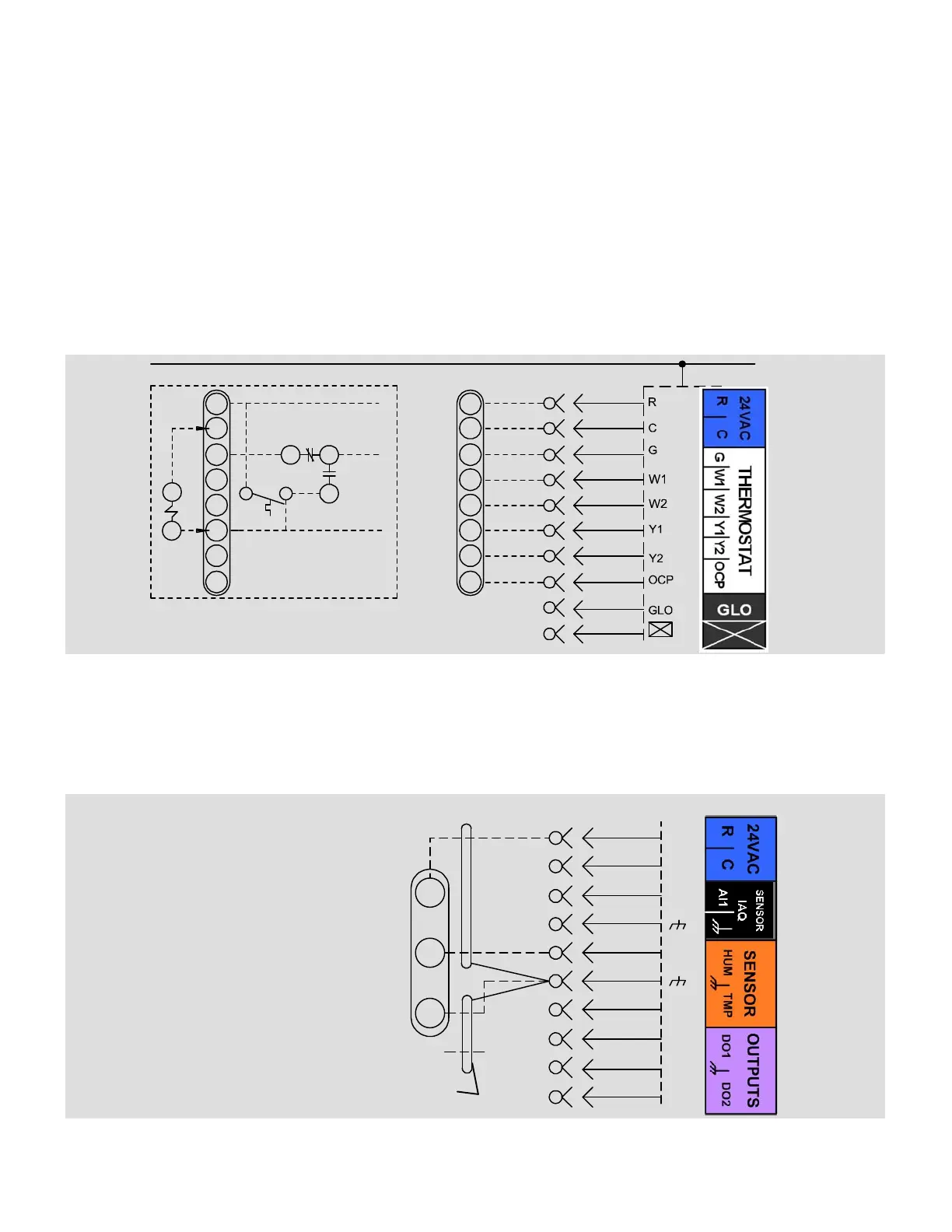
A de−humidistat will bring on first−stage cooling to dehumidify and a room thermostat will energize heating to maintain indoor
temperature. To disable free cooling in this mode, select economizer global mode (figure 9) but do not connect the global
input (P297−9).
An optional de−humidistat is required. Refer to figure 5.
K55
B
A
K55−1
7
5
2
S86
P297
J297A
1
2
B
3
4
5
6
7
8
C
9
10
R
OCP
C
G
W1
W2
Y1
Y2
24 V POWER
A55
TO R
TO G
TO Y1
TO M2 THERMOSTAT INPUTS
ALL OTHER THERMOSTAT
SIGNALS REMAIN CONNECTED
AS SHOWN ON THE RIGHT.
TO PROVIDE SUPERMARKET REHEAT SCHEME, USE
S86 DEHUMIDISTAT AND K55 RELAY
R
OCP
C
G
W1
W2
Y1
Y2
Figure 5. Supermarket Reheat Diagram (ECTO 4.24 Option 1)
ECTO 4.24 Option 2 RH Sensor Control
A relative humidity sensor will bring on first−stage cooling based on the setpoint set with ECTO 4.25 or from the L Connection
network. First−stage cooling will de−energize when RH drops to ECTO 4.25 minus 4.26. A room thermostat or zone sensor
will energize heating to maintain indoor temperature.
An optional RH sensor is required. Refer to figure 6.
A91 HUMIDITY SENSOR
0 − 10VDC = 0−100% RH
Two separate shielded cables required.
One wire of the two
pairs is not connected.
P298
J298A
1
2
B
3
4
C
5
6
7
D
8
9
10
A91
VIN
VO
GND
R
C
AI−1
HUM
TMP
DO−1
C
DO−2
Figure 6. Reheat Sensor Diagram