17. Electronic Configure To Order (ECTO) Control Parameters
Page 69
PRODIGYT M2 UNIT CONTROLLER
Control Parameter
No. Name
DescriptionUnits
Control Value
Min. Default Max.
B, C, D, & E BOXES Block 0 VAV, CAVB, & MSAV Parameters (continued)
0.23
DO_Mode_
A133_(VAV
mode)
0 0 127 Option
A133 (w/DIP set to VAV) Digital Out Mode = X + 32*Y + 16*Z
Input source= X:
0− None. Output enables exhaust fan stage 2.
1− Compressor 1 duty cycle. (Compressor crankcase heater func-
tion.) On when OAT <= ECTO 0.24 and >= ECTO 0.25 seconds
have passed with compressor 1 off. Off when OAT > ECTO 0.24
+ 3 deg F (fixed deadband) or < ECTO 0.25 sec have passed
with compressor 1 off.
2− On when occupied.
3− On when blower on.
4− On when heating demand.
5− On when cooling demand.
6.− On when heating or cooling demand.
7− System RH (A55_P298_5 RH)
8− System IAQ. (A55_P298_3 IAQ)
9− System OAT (A55_P267_1/2 OAT)
10− AI1. (A133_P194−6).
11− AI2. (A133_P194−7).
12− AI3. (A133_P194−8).
13− AI4. (A133_P194−9).
14− AO1. (A133_P194−11).
15 AO2. (A133_P194−12).
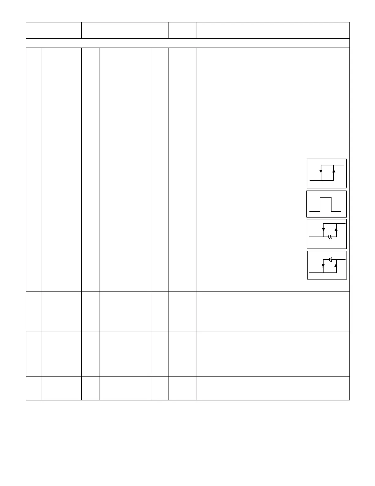
Algorithm Y for input sources 7−15:
0− Hysteresis loop
On when input >= ECTO 0.24
Off when input < ECTO 0.24−ECTO 0.25
1− Window
On when input is in range; >= ECTO 0.24
and <= ECTO 0.24 + ECTO 0.25
(Fixed 3−count hysteresis loop on rising
and falling edges of window.)
2− Delayed−on.
On when input is >= ECTO 0.24
for >= ECTO 0.25 seconds.
Off when input is < ECTO 0.24 − 3.
(Fixed 3−count hysteresis loop on edge.)
3− Delayed−off.
On when input is >= ECTO 0.24.
Off when input is < ECTO 0.24 − 3
for >= ECTO 0.25 seconds.
(Fixed 3−count hysteresis loop on edge.)
Inversion Z:
0 − Output not inverted.
1 − Output inverted.
0.24−0.25
ON
OFF
OFF
0.24+0.25
0.24
O
N
OFF
ON
DELAY
0.25
0.24
OFF
ON
0.24
DELAY
0.25
OFF
0.24
Graphs indicate output not
inverted. See figure 33.
0.24
DO_SP_
A133_
(VAV mode)
0
0
0
0
132
−.05
0
127
5.0
996
100
51
0
2.5
255
10.0
2000
100
−31
0.5
5.0
Counts
R:Volts
I:ppm
P:%
Y:DegF
M:"w.c.
N:"w.c.
A133 (w/DIP set to VAV) digital output mode setpoint
0.25
DO_DB_A133_
(VAV mode)
2
0
16
2
1
64
0.01
0
13
.50
102
13
8
416
0.05
.25
255
10.0
2000
100
162
8160
1.0
5.0
Counts
R:Volts
I:ppm
P:%
O:DegF
D:Sec.
L:"w.c.
N:"w.c.
A133 (w/DIP set to VAV) digital output mode deadband or delay.
0.26
Supply_Static-
Sensor_Low_
Alarm_Check
30
30
40
40
101
101
Count
P:%
Supply Static Pressure Sensor (A30) connected at (A133_P195_6)
(TB18_6) alarm threshold. Blower percent speed before checking
sensor after a 20 second delay. A value of 101 disables the low
threshold or open" alarm trap.
table continued on next page

 Loading...


