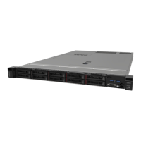
Figure 8. Ten 2.5-inch hot-swap drives model front view
Note: The last two drive bays may not be supported if only the eight-bay backplane is installed.
Table 6. Components on the ten 2.5-inch hot-swap drives model front view
1 USB 2.0 connector 4 VGA connector (optional)
2 USB 3.1 Gen 1 connector 5 Ten 2.5-inch hot-swap drive bays (0-9)
3 Front operator panel 6 Rack release latches
Front operator panel
The front operator information panel of the server provides controls, connectors, and LEDs. The front
operator panel varies by model.
Figure 9. 2.5-inch drive chassis front I/O assembly
Figure 10. 3.5-inch drive chassis front operator panel
Table 7. Front operator panel controls and indicators
1 Power button and power LED (green) 4 System ID button/LED (blue)
2 Drive activity LED (green) 5 System-error LED (yellow)
3 Network activity LED (green)
1 Power button and power LED (green): Press this button to turn the server on and off manually. The
states of the power LED are as follows:
Off: Power is not present or the power supply, or the LED itself has failed.
16
ThinkSystem SR250 Setup Guide

 Loading...


