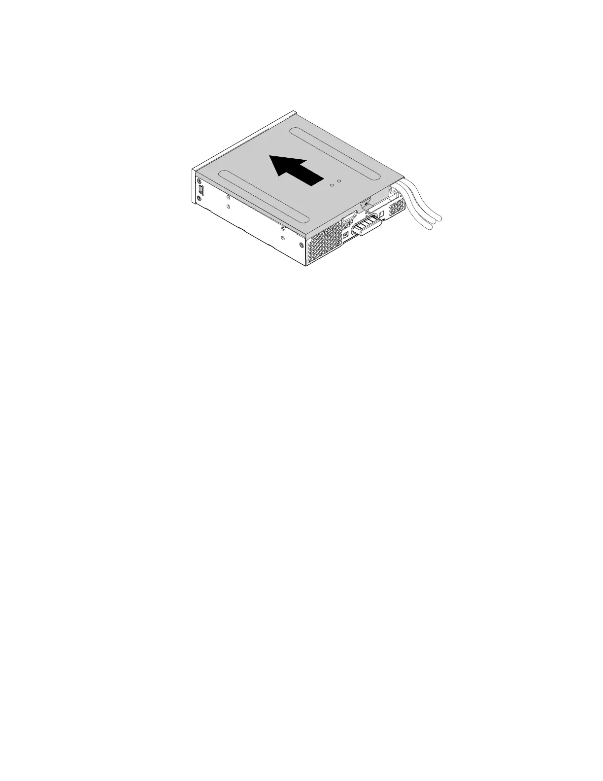
7. Position the flex module cover on the flex module. Ensure that the rail guides on the bottom of the cover
engage the rails on the flex module. Then, push the cover to the front of the flex module until it snaps
into position.
Figure 167. Reinstalling the flex module cover
8. Install the flex module into the flex bay.
9. Refer to the recorded information about the cable connections and routing, reconnect all cables
connected to the flex module to the system board. See “Parts on the system board” on page 38. For the
eSATA connector or an IEEE 1394 connector, do either of the following:
• Connect the eSATA connector to the eSATA/SATA connector on the system board.
• Connect the IEEE 1394 connector cable to the IEEE 1394 adapter.
10. Reconnect any removed cables to the flex module.
What to do next:
• To work with another piece of hardware, go to the appropriate section.
• To complete the installation or replacement, go to “Completing the parts replacement” on page 187.
Front Thunderbolt adapter kit
The front Thunderbolt adapter kit includes the following parts:
• A front Thunderbolt I/O adapter
• A front Thunderbolt PCIe x4 card
• A bezel
• A general-purpose input/output(GPIO) cable
• A mini-SAS cable
• An internal DP-to-DP cable
• An external DP-to-DP cable
To remove or install a front Thunderbolt adapter kit, do the following:
1. Prepare your computer. See “Preparing your computer” on page 98.
2. Record the cable connections and cable routing. Then disconnect all cables connected to the system
board and the front Thunderbolt PCIe x4 card.
3. Remove the flex module out of the chassis. See “Device in the flex bay” on page 117.
Chapter 9. Hardware removal and installation 183