9300 Servo PLC
System blocks
2.8 DFIN_IO_DigitalFrequency
2-27
L
ServoPLC EN 2.0
Confifugration of increments
• The drive can be adapted to the connected encoder or preconnected controller with master
frequency cascade or master frequency bus via under C0425.
Code LCD
Possible settings
Info
Lenze Selection
C0425 DFIN const 3 Increments of the encoder input
0 256 increments per revolution
1 512 increments per revolution
2 1024 increments per revolution
3 2048 increments per revolution
4 4096 increments per revolution
5 8192 increments per revolution
6 16384 increments per revolution
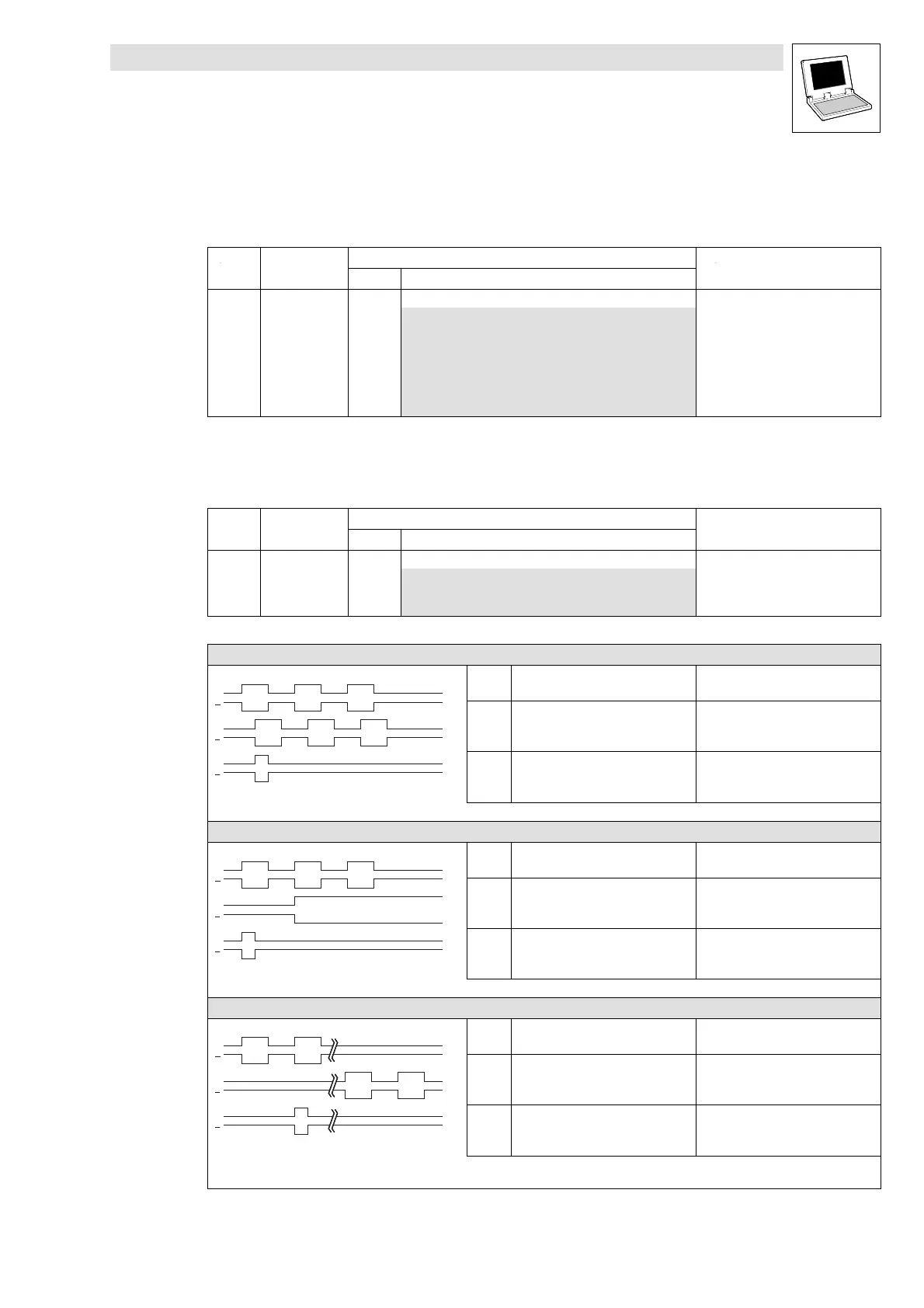
Configuration of digital frequency input signal
• Use C0427 to configure the type of the digital frequency input signal:
Code LCD
Possible settings
Info
Lenze Selection
C0427 DFIN function 0 Type of the digital frequency signal
0 2 phases
1 A = Speed / B = Direction
2 A or B = Speed or direction
C0427 = 0 (2 phases)
B
B
A
A
Z
Z
CW rotation: CCW rotation:
B
B
A
A
Z
Z
Track
A
leads track B by 90º
( DFIN_nIn_v = positive value
lags behind track B by 90º
( DFIN_nIn_v = negative value)
B
B
A
A
Z
Z
Track
B
- -
Signal sequence with phase shift (CW rotation)
C0427 = 1 (A = speed / B = direction)
B
B
A
A
Z
Z
CW rotation: CCW rotation:
B
B
A
A
Z
Z
Track
A
transmits the speed transmits the speed
B
B
A
A
Z
Z
Track
B
= FALSE
( DFIN_nIn_v = positive value
=TRUE
( DFIN_nIn_v = negative value)
Control of the direction of rotation by track B
C0427 = 2 (A or B = speed or direction)
B
B
A
A
Z
Z
CW rotation: CCW rotation:
B
B
A
A
Z
Z
Track
A
transmits speed and direction
( DFIN_nIn_v = positive value
= FALSE
B
B
A
A
Z
Z
Track
B
= FALSE transmits speed and direction
( DFIN_nIn_v = negative value)
Control of speed and direction of rotation
via track A or track B
efesotomasyon.com - Lenze

 Loading...


