9300 Servo PLC
Preface and general information
1-8
L
ServoPLC EN 2.0
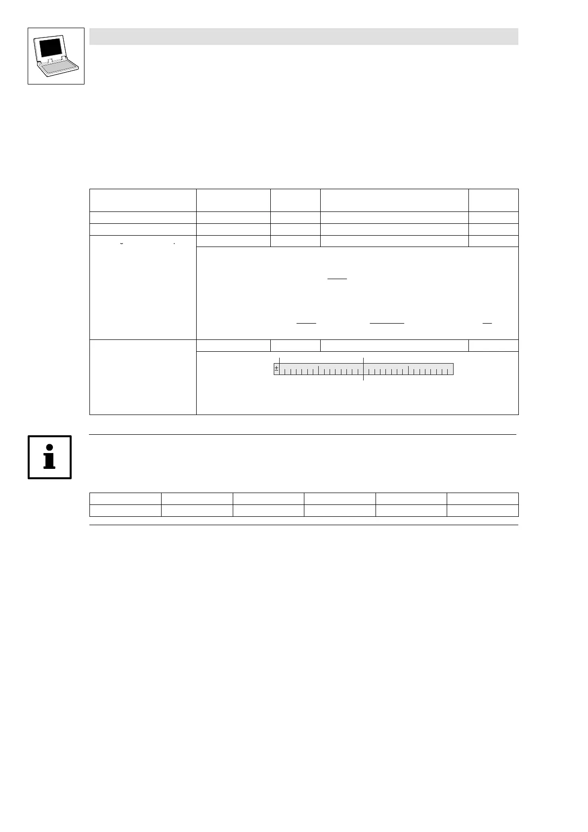
1.2.7 Signal types and normalisations
Most inputs and outputs of Lenze function blocks/system blocks can be assigned to a certain signal
type. We distinguish between digital, analog, position and speed signals.
The identifier of the corresponding input/output variable has an ending (starting with an underscore)
which indicates the signal type.
Signal type Ending Memory
location
Normalisation
(external ≡
≡≡
≡ internal)
Previous
designation
analog _a (analog) 16 bit 100 % ≡ 16384 H
digital _b (binary) 8bit 0 ≡ FALSE; 1 ≡ TR UE G
Phase-angle difference or speed
_v (velocity) 16 bit 15000 rpm ≡ 16384 F
• Phase difference/speed ref. to 1 ms
• Normalisation example:
1 motor revolution = 65536 [inc]
Variable value (..._v) =
15000
60 [s]
⋅ 65536 [inc] =
15000
60000 [ms]
⋅ 65536 [inc] = 16384
inc
ms
Speed (motor) = 15000 [rpm] =
15000
60 [s]
Phase-angle or position _p (position) 32 bit 1 motor revolution ≡ 65536 E
High Word Low Word 031
Direction (0 ≡ CW; 1 ≡ CCW)
No. of motor revolutions (0 ... 32767)
Phase or angle (0 ... 65535)
Note!
Because of their normalisation, analog signals use an unsymmetrical resolution area.
(-200 % ... +199.99 %):
External: -200 % -100 % 0 +100 % +199.99 %
Internal: -32768 -16384 0 +16384 +32767
efesotomasyon.com - Lenze

 Loading...


