13
ENGLISH
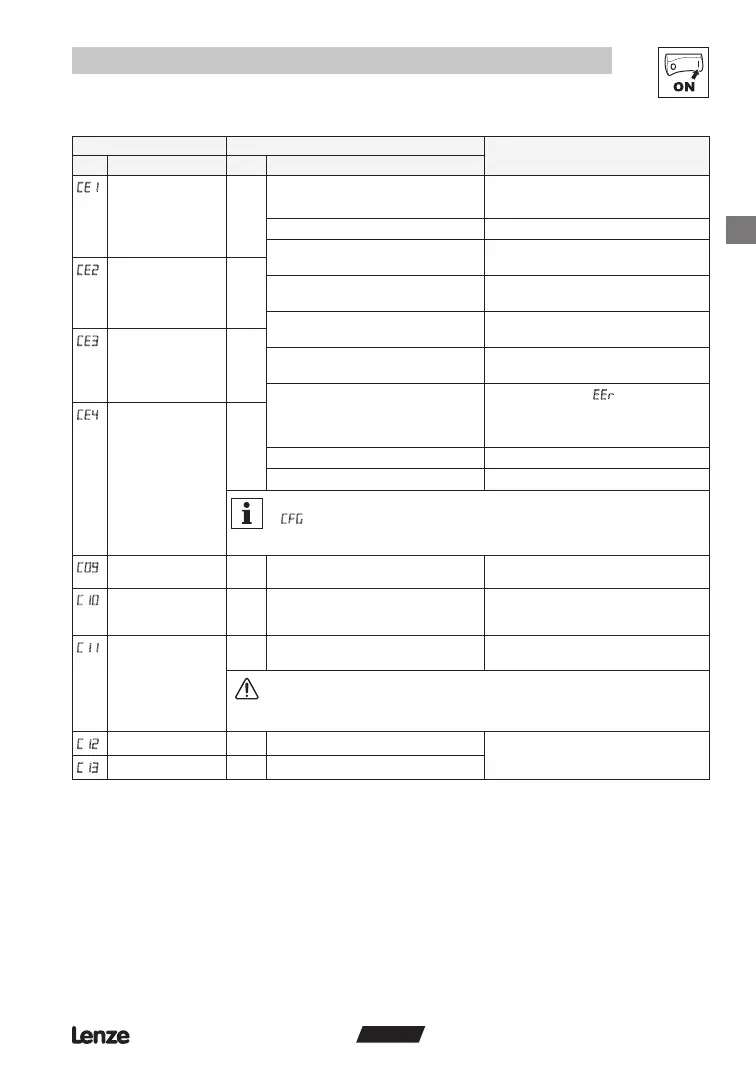
Commissioning
Code Possible Settings
IMPORTANT
No. Name Lenze Selection
Configuration -
Digital input E1
1 1 Activate xed setpoint 1 (JOG1)
Activate JOG3: Both terminals = HIGH
2 Activate xed setpoint 2 (JOG2)
3 DC braking (DCB) see also C36
4 Direction of rotation LOW = CW rotation
HIGH = CCW rotation
Configuration -
Digital input E2
2
5 Quick stop Controlled deceleration to standstill, active
LOW; Set decel rate in C13 or c03
6 CW rotation
7 CCW rotation
CW rotation = LOW and CCW rotation =
LOW: Quick stop; Open-circuit protected
Configuration -
Digital input E3
3
8 UP (setpoint ramp-up)
9 DOWN (setpoint ramp-down)
UP = LOW and DOWN = LOW: Quick stop;
Use momentary NC contacts
10 TRIP set
Active LOW, triggers
(motor coasts to
standstill)
NOTE: NC thermal contact from the motor
can be used to trigger this input
Configuration -
Digital input E4
4
11 TRIP reset see also c70
12 Accel/decel 2 see c01 and c03
Note
A
fault will occur under the following conditions:
• E1...E4 settings are duplicated (each setting can only be used once)
• One input is set to UP and another is not set to DOWN, or vice-versa
Network address 1 1 247 Each controller on network must have
unique address
C1
Minimum output
frequency
0.0 0.0 {Hz} 240 • Output frequency at 0% analog setpoint
• C10 not active for xed setpoints or
setpoint selection via c40
Maximum output
frequency
50.0 7.5 {Hz} 240 • Output frequency at 100% analog setpoint
• C11 is never exceeded
WARNING!
Consult motor/machine manufacturer before operating above rated frequency.
Overspeeding the motor/machine may cause damage to equipment and injury to
personnel!
Acceleration time 1 5.0 0.0 {s} 999 • C12 = frequency change 0 Hz...C11
• C13 = frequency change C11...0 Hz
• For S-ramp accel/decel, adjust c82
Deceleration time 1 5.0 0.0 {s} 999