Fast commissioning steps at a glance
Leuze electronic BPS 34 9
TNT 35/7-24V
Note!
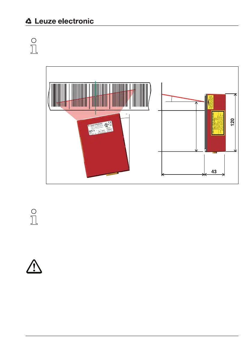
The installation dimensions listed in the following figure must absolutely be adhered to. Opti-
cally, it must be ensured that the scanner has an unobstructed view of the bar code tape at
all times.
Chapter 7.2 on Page 41
Figure 3.1:Beam exit and device arrangement of the BPS 34
Chapter 7.1 on Page 38
Note!
During mounting, the following angles of inclination must be taken into account in the vertical
axis:
10° for a tape height of 47mm,
7° for a tape height of 30mm and
5° for a tape height of 25mm;
the working range of the reading field curve must also be taken into account.
Attention!
For the position calculation, the scanning beam of the BPS 34 must be incident on the bar
code tape without interruption. Ensure that the scanning beam is always incident on the bar
code tape when the system is moving.
2
2
1
Reading distance
Beam exit
all dimensions
in mm
Bar code tape
Center of the scanning beam
(device center, output position value)
Scanning beam
10° pitch
in the
vertical axis
(dependent on
the tape height,
see notes)