MS 34 … / MSD 1 101 connection units
Leuze electronic BPS 34 25
TNT 35/7-24V
5.1.4 Electrical connection
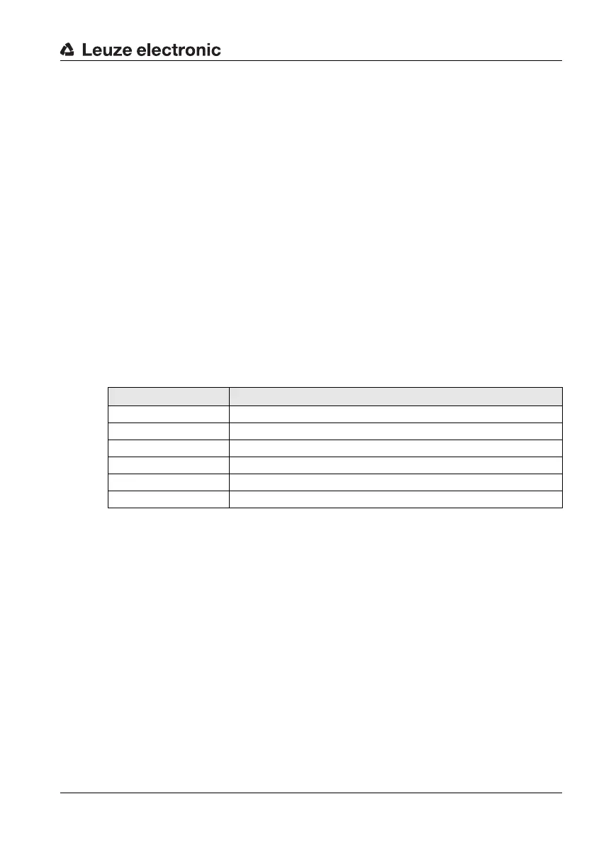
5.1.5 Description of the LED states
MS 34 103 / MS 34 105
A status LED is located between the M12 connectors DP IN and DP OUT on the modular
connector hood. It indicates the state of the PROFIBUS connection.
2) Note: The LED remains off until the BPS 34 is recognized by the PROFIBUS. Only after
the PROFIBUS has addressed the BPS 34 for the first time, the following state descrip-
tions apply.
Electrical data
Interface type PROFIBUS DP, up to 12MBd
Service interface
1)
1) Only in combination with the MS 34 105 and MSD 1 101 devices
RS232 with default data format,
9600Bd, 8 data bits, no parity, 1 stop bit
Switching input / switching
output
1 switching input, 1 switching output, each is programma-
ble
Operating voltage Without optics heating: 10 … 30VDC
With optics heating: 22 … 26VDC
Power consumption Without optics heating: 5W
With optics heating: max. 30W
State Meaning
Off Voltage off or device not yet recognized by the PROFIBUS
2)
Green, flashing Initialization of the device, establishing the PROFIBUS communication
Green, continuous light Data operation
Red, flashing Error on the PROFIBUS, error can be resolved by a reset of the control
Red, continuous light Error on the PROFIBUS, error cannot be resolved by a reset of the control
Orange, continuous light Service operation active