Technical data of BPS 34
Leuze electronic BPS 34 19
TNT 35/7-24V
4.3.1 PWR IN - voltage supply and switching input/output
Attention!
For devices with integrated heating, the supply voltage must be wired with a minimum
0.5mm
2
(recommended 0.75mm
2
) core cross section. It is not possible to loop the
supply voltage through to other loads!
Note!
Cables with a wire cross section of 0.5mm² or 0.75mm² are not available as ready-made
cables from Leuze electronic.
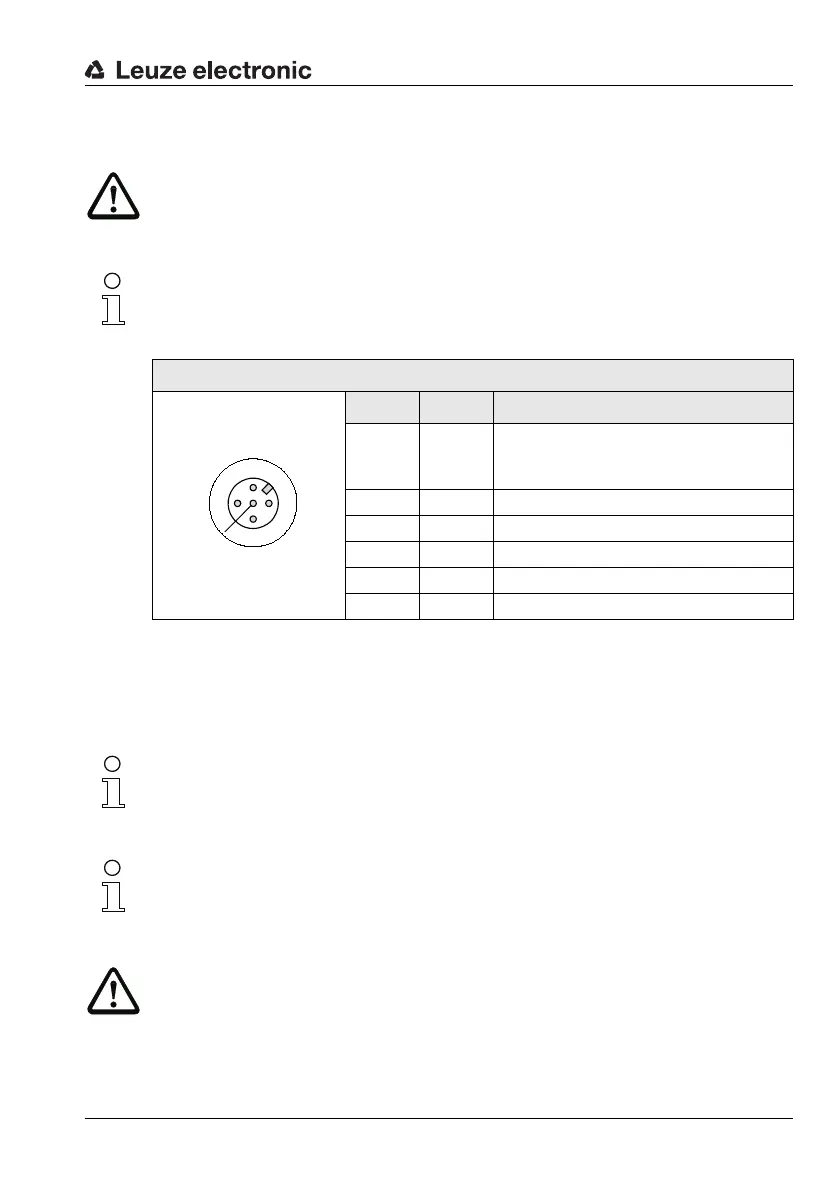
Figure 4.4:Pin assignment - PWR IN
Connecting the functional earth PE
BPS 34 with MS 34 103/MS 34 105 connector hood:
Connect PE to PIN 5 of the M12 connector PWR IN for voltage supply!
Note!
Programming of the switching input/switching output is performed via module 7 (Switching
input) and module 8 (Switching output). For further information, see also Chapter 8.1.7.7,
Page 60 et seq.
Note!
The switching input/switching output of the PWR IN plug connection is identical to the SWIN
switching input and SWOUT switching output of the SW IN/OUT plug connection on the
MS 34 105.
Attention!
Degree of protection IP 65 is achieved only if the connectors and caps are screwed into
place!
PWR IN (5-pin plug, A-coded)
Pin Name Comment
1VIN
Positive supply voltage
Without optics heating: +10 … +30VDC
With optics heating: +22 … +26VDC
2 SWOUT Switching output
3 GND Negative supply voltage 0VDC
4 SWIN Switching input
5 PE Functional earth
Thread PE Functional earth (housing)
PWR IN
SWIN
SWOUT
3
2
1
4
GND VIN
PE