Mounting
Leuze electronic BPS 34 41
TNT 35/7-24V
7.2 Device arrangement
Selecting a mounting location
In order to select the right mounting location, several factors must be considered:
• The scanning range determined from the scanning curve must be adhered to at all
areas at which a position determination is to be made
• The BPS should be mounted at an angle of 10° (depending on the tape height, see
note Page 40) in the vertical axis towards the bar code tape to ensure continued reli-
able positioning results even the bar code tape is soiled.
• On the BPS 34, the beam is not emitted perpendicular to the cover of the housing, but
with an angle of 10° towards the top. This angle is intended to prevent total reflection
on the bar code tape. This beam exit is already integrated in the device. As a result,
the BPS can be at the minimum reading distance and mounted parallel to the bar
code tape.
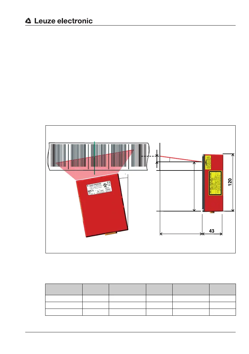
Figure 7.4:Beam exit and device arrangement of the BPS 34
Dimension X in Figure 7.4 shows the mounting height of the BCB center relative to the
housing of the BPS 34. Dimension X is dependent on the reading distance. Please refer to
the following table for the value:
Reading distance
[mm]
Dim. X [mm]
Reading distance
[mm]
Dim. X [mm]
Reading distance
[mm]
Dim. X [mm]
90 16 120 21 150 26
100 18 130 23 160 28
110 19 140 25 170 30
2
2
1
Reading distance
Beam exit
all dimensions in mm
Bar code tape
Center of the scanning beam
(device center, output position value)
Scanning beam
10° pitch
in the
vertical axis
(dependent on
the tape height,
see notes)