Technical data of BPS 34
Leuze electronic BPS 34 21
TNT 35/7-24V
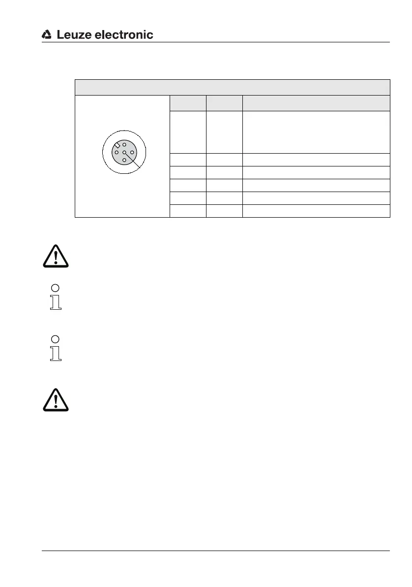
4.3.4 SW IN/OUT – Switching input/switching output
Figure 4.7:Pin assignment - SW IN/OUT
Attention!
Degree of protection IP 65 is achieved only if the connectors and caps are screwed into
place!
Note!
Programming of the switching input/switching output is performed via module 7 (Switching
input) and module 8 (Switching output). For further information, see also Chapter 8.1.7.7,
Page 60 et seq.
Note!
The switching input/switching output of the PWR IN plug connection is identical to the SWIN
switching input and SWOUT switching output of the SW IN/OUT plug connection on the
MS 34 105.
Attention!
If you use a sensor with a standard M 12 connector, please note the following:
Only use sensors on which the switching output does not lie on pin 2, i.e. only sensor cables
on which pin 2 is not assigned. Otherwise, the switching output is not protected against feed-
back on the switching input. If the inverted sensor output lies on pin 2, for example,
erroneous behavior of the switching output will result!
SW IN/OUT (5-pin socket, A-coded)
Pin Name Comment
1VOUT
Supply voltage for sensor system
(VOUT identical to VIN at PWR IN)
Without optics heating: +10 … +30VDC
With optics heating: +22 … +26VDC
2 SWOUT Switching output
3 GND Supply voltage for sensors 0VDC
4 SWIN Switching input
5 PE Functional earth
Thread PE Functional earth (housing)
SW IN/OUT
1
2
3
4
VOUT
PE
SWIN
SWOUT
GND