Mounting / Installation (all device models)
Leuze electronic DDLS 200 19
TNT 35/7-24V
4.4.2 Electrical connection - devices with M12 connectors
The electrical connection is easily performed using M12 connectors. Ready-made connection cables
are available as accessories both for connecting supply voltage/switching input/switching output as
well as for connecting the respective bus system (see chapter 14 "Accessories").
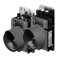
For all M12 device models, the supply voltage, the switching input and the switching output are con-
nected via the right, A-coded connector PWR IN (see Figure 4.6).
Figure 4.6: Position and designation of the M12 connections
Figure 4.7: Assignment M12 connector PWR IN
PWR IN (5-pin M12 connector, A-coded)
Pin Name Comment
1Vin
Positive supply voltage
+18 … +30VDC
2
OUT
WARN
Switching output, activated if level drops below the
warning level
3 GND Negative supply voltage 0VDC
4IN
Switching input for transmitter/receiver switch-off:
0…2VDC: Transmitter/receiver switched off, no
transmission
18 … 30VDC: transmitter/receiver active, normal
function
5 FE Functional earth
Thread FE Functional earth (housing)
BUS OUTBUS IN
All M12 device models: PWR IN
M12 connector, A-coded
PWR IN
IN
OUT
WARN
3
2
1
4
GND Vin
FE
DDLS200_E.book Seite 19 Mittwoch, 19. Februar 2020 12:22 12
 Loading...