INTERBUS 500kBit/s / RS 422
Leuze electronic DDLS 200 27
TNT 35/7-24V
Device configuration RS 422
General RS 422 protocols can be transmitted with the DDLS 200. No baud rate setting is necessary
(max. 500kBit/s). The shielding connection can be set via switch S4 as with the INTERBUS.
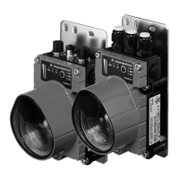
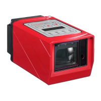
6.3 LED indicators INTERBUS 500kBit/s / RS 422
In addition to the indicators and operational controls present in all device models (bar graph, buttons,
LEDs AUT, MAN, ADJ; see chapter 11.1 "Indicators and operational controls"), the INTERBUS model
also has the following indicators:
Figure 6.4: Indicators and operational controls of the INTERBUS model
NOTE
The delay time of a light path is approx. 1.5 µs (depending on the distance).
LED PWR: green = operation indicator
green flashing= transmitter / receiver unit switched off
via switching input IN or hardware error
off = no operating voltage
LED Tx: green = data is being transmitted to the bus
green flashing= with baud rates set to very low values,
the LEDs Tx and Rx flicker. At very
high baud rates (> 50kBit/s), flashing
LEDs Tx and Rx indicate faulty bus
communication.
off = no data on the transmission line
LED Rx: green = data is being received by the bus
green flashing= with baud rates set to very low values,
the LEDs Tx and Rx flicker. At very
high baud rates (> 50kBit/s), flashing
LEDs Tx and Rx indicate faulty bus
communication.
off = no data on the receiving line
DDLS200_E.book Seite 27 Mittwoch, 19. Februar 2020 12:22 12
 Loading...