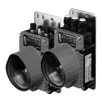
PROFIBUS / RS 485
Leuze electronic DDLS 200 21
TNT 35/7-24V
5 PROFIBUS / RS 485
The PROFIBUS model of the DDLS 200 has the following features:
• Operating ranges 30m, 80m, 120m, 200m, 300m, 500m
• Electrically isolated interface
• The DDLS 200 does not occupy a PROFIBUS address
• Integrated repeater function (signal processing), can be switched off
• Protocol-independent data transmission, i.e. transmission of the FMS, DP, MPI,
FMS/DP mixed operation protocols, PROFISAFE
• 2 connection variants: clamp connection with screwed cable glands or M12 connectors
• Connectable bus terminator (termination), or ext. terminator plug on the M12 model
• 6 baud rates configurable (see Chapter 5.3)
• Optional M12 connector set for conversion available as accessory
• Cascading of several DDLS 200 is possible (see Chapter 4.3)
5.1 PROFIBUS connection - devices with screwed cable glands and terminals
The electrical connection to the PROFIBUS is made at the terminals A, B, and COM. The terminals
A’, B’ and COM are provided for wiring through the bus.
Figure 5.1: Connection board of the PROFIBUS model with terminals and screwed cable glands
S2
S1
COM
COM
A'
B'
OUT
WARN
PE
GND
Vin
IN
PE
GND
Vin
SHIELD AREA
BS
A400A
Term.
Off
On
COM
COM
+'
Off
On
IN
On =
RS 485
Off =
Profibus
S3
Off
On
0
1
PROFIBUS - terminals and switches
Terminal Function
A , – (N) PROFIBUS or (–) RS 485
B, + (P) PROFIBUS or (+) RS 485
COM Potential equalization
A’, –’ (N) PROFIBUS or (–) RS 485 of the
continuing bus
B’, +’ (P) PROFIBUS or (+) RS 485 of the
continuing bus
Switch Function
S2 Termination On/Off
S3-1 … S3-3 Setting the baud rate of the PROFIBUS
segment
S3-4 Changeover PROFIBUS (Off) /
RS 485 (On)
DDLS200_E.book Seite 21 Mittwoch, 19. Februar 2020 12:22 12
 Loading...