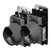
PROFIBUS / RS 485
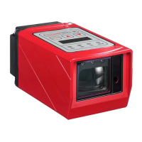
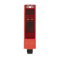
Leuze electronic DDLS 200 23
TNT 35/7-24V
Figure 5.4: Assignment M12 connector BUS OUT
Termination for devices with M12 connectors
5.3 Device configuration PROFIBUS
Termination for devices with screwed cable glands and terminals
The PROFIBUS can be terminated via the switch S2 in the DDLS 200. If the termination is active
(S2 = On), internal bus resistors are connected as per the PROFIBUS standard and the PROFIBUS
is not wired through at terminals A’ and B’.
Activate the termination when the PROFIBUS segment begins or ends at the DDLS 200. The default
setting is termination inactive (S2 = Off).
Adjustment of the transmission rate
You must set the transmission rate of your PROFIBUS segment using the three DIP switches S3-1
through S3-3. Possible transmission rates are:
• 9.6 kBit/s • 19.2 kBit/s
• 93.75 kBit/s • 187.5 kBit/s
1)
• 500 kBit/s
1)
• 1500 kBit/s
1)
Set the transmission rate in accordance with the table printed on the connection board (see figure 5.1).
The default settings are:
• 9.6kBit/s for DDLS 200 PROFIBUS device models with clamp connection
• 1500kBit/s for DDLS 200 PROFIBUS device models with M12 connection
BUS OUT (5-pin M12 socket, B-coded)
Pin Name Comment
1VCC5VDC for bus termination
2A (N)Receive/transmit data A-line (N)
3GNDPData reference potential
4B (P)Receive/transmit data B-line (P)
5NCNot assigned
Thread FE Functional earth (housing)
NOTE
If the PROFIBUS network begins or ends at the DDLS 200 (no continuing bus), the
BUS OUT connection must be terminated with the TS 02-4-SA terminator plug, which is
available as an optional accessory (see chapter 14.1 on page 66).
In this case, please also order the TS 02-4-SA terminator plug.
1) Not for 500 m operating range!
BUS OUT
VCC
1
2
3
4
A (N)
B (P)
GNDP
NC
DDLS200_E.book Seite 23 Mittwoch, 19. Februar 2020 12:22 12
 Loading...