INTERBUS 2MBit/s FOC
30 DDLS 200 Leuze electronic
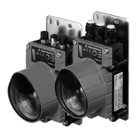
Figure 7.2: Connection of the DDLS 200 to the INTERBUS (fiber-optic cable)
7.2 Device configuration INTERBUS 2MBit/s FOC
Changeover transmission rate (default: ’2M’)
In the DDLS 200, switch S2 must be used to specify in the transmission rate of the FOC INTERBUS:
Switch S2 Position 500k: transmission rate 500 kBit/s.
Position 2M (default): transmission rate 2 MBit/s.
Changeover incoming/outgoing bus (default: ’In Bus’)
Switch S3 must be used to specify in the DDLS 200 whether the connected FOC is for the incoming
bus (In Bus) or outgoing bus (Out Bus):
Switch S3 Position In Bus (default): incoming bus FOC, outgoing bus optical data transmission.
Position Out Bus: incoming bus optical data transmission, outgoing bus FOC.
7.3 LED indicators INTERBUS 2MBit/s FOC
In addition to the indicators and operational controls present in all device models (bar graph, buttons,
LEDs AUT, MAN, ADJ; see chapter 11.1 "Indicators and operational controls"), the INTERBUS model
also has the following indicators:
NOTE
The delay time of a light path is approx. 2.5 µs.
Switch S3
Position In Bus
Switch S3
Position Out Bus
Incoming bus Outgoing bus
Participant
Connection group
FOC bus ter-
minal
FOC
Participant
FOC
H1
H2
H2
H1
DDLS200_E.book Seite 30 Mittwoch, 19. Februar 2020 12:22 12
 Loading...