Ethernet
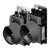
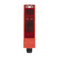
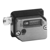
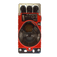
Leuze electronic DDLS 200 55
TNT 35/7-24V
DDLS 200 between end device/PLC and end device/PLC
Figure 10.7: DDLS 200 between end device/PLC and end device/PLC
10.4.1 Assignment of the RJ45 and M12 Ethernet cables
For the Ethernet models of the DDLS 200, the following pin assignments apply for the RJ45 and M12
connection cables.
RJ45 to RJ45 - 1 : 1
RJ45 to RJ45 - Crossover
M12 connector - D-coded with open cable end
Signal Function Core color Pin RJ45 Pin RJ45
TD+ Transmit data + Yellow 1 / TD+ <–> 1 / TD+
TD- Transmit Data – Orange 2 / TD- <–> 2 / TD-
RD+ Receive data + White 3 / RD+ <–> 3 / RD+
RD- Receive data – Blue 6 / RD- <–> 6 / RD-
Signal Function Core color Pin RJ45 Pin RJ45
TD+ Transmit data + Yellow 1 / TD+ <–> 3 / RD+
TD- Transmit Data – Orange 2 / TD- <–> 6 / RD-
RD+ Receive data + White 3 / RD+ <–> 1 / TD+
RD- Receive data – Blue 6 / RD- <–> 2 / TD-
Signal Function Core color Pin M12 Core
TD+ Transmit data + Yellow 1 / TD+ <–> YE
TD- Transmit Data – Orange 3 / TD- <–> OG
RD+ Receive data + White 2 / RD+ <–> WH
RD- Receive data – Blue 4 / RD- <–> BU
End device / PLC
Optical data transmission
End device / PLC
Crossover cable Crossover cable
DDLS200_E.book Seite 55 Mittwoch, 19. Februar 2020 12:22 12
 Loading...