Mounting / Installation (all device models)
12 DDLS 200 Leuze electronic
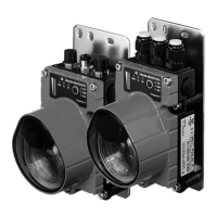
4.2 Arrangement of adjacent transmission systems
To prevent mutual interference of adjacent transmission systems, the following measures should be
taken in addition to exact alignment:
Figure 4.2: Arrangement of adjacent transmission systems
NOTE
The fine alignment of the transmission system is performed during commissioning (see
chapter 11.3.2 "Fine alignment"). The position of the optical axis of the DDLS 200 can be
found in chapter 3.2.
DDLS 200/XXX.1-YY DDLS 200/XXX.2-YY
DDLS 200/XXX.1-YY DDLS 200/XXX.2-YY
( frequency f1 ) ( frequency f2 )
( frequency f
2 ) ( frequency f1 )
( frequency f
1 ) ( frequency f2 )
DDLS 200/XXX.1-YYDDLS 200/XXX.2-YY
min. 400 mm (DDLS 200/30…)
min. 300 mm (DDLS 200/80…)
min. 300 mm (DDLS 200/120…)
min. 500 mm (DDLS 200/200…)
min. 700 mm (DDLS 200/300…)
min. 700 mm (DDLS 200/500…)
Frequency-offset arrangement!
min. tan (0.5°) • operating
range
(DDLS 200/120…500…)
min. tan (1.0°) • operating
range
(DDLS 200/80…)
Identical frequency arrange-
ment
DDLS200_E.book Seite 12 Mittwoch, 19. Februar 2020 12:22 12
 Loading...