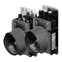
DeviceNet / CANopen
40 DDLS 200 Leuze electronic
Figure 9.7: Assignment M12 connector BUS OUT
Via the selector switch S2, the bus transceiver can optionally be supplied via Power or V+ / V-.
S2 = Vin (default) bus transceivers are supplied internally
S2 = BUS, bus transceivers are supplied via V+/V-.
Termination
BUS OUT (5-pin M12 socket, A-coded)
Pin Name Comment
1DrainShield
2V+
Positive supply bus transceiver
(switch S2 = bus)
3V-
Negative supply bus transceiver
(switch S2 = bus)
4CAN_HBus signal High
5CAN_LBus signal Low
Thread FE Functional earth (housing)
ATTENTION!
The supply voltage V+ / V- is 11 … 25 V DC.
NOTE
If the CANopen or DeviceNet network begins or terminates at the DDLS 200 (not a
continuing bus), the BUS OUT connection must be terminated with the TS01-5-SA termi-
nator plug (Part No. 50040099), which is available as an option.
In this case, please also order the TS 01-5-SA terminator plug.
BUS OUT
CAN_H
V+
3
2
1
4
V-Drain
CAN_L
DDLS200_E.book Seite 40 Mittwoch, 19. Februar 2020 12:22 12
 Loading...