1. If communication over the RS485 bus is used, check the address settings of the potentiometers on
the front panel of the converter (see Figure 13c).
The total address is: “High ADRS” x 10 + “Low ADRS” x 1
2. The Levitronix
®
Service Software can be used to debug and configure the flowmeter over the RS485.
For communication with RS485 the MODBUS protocol can be requested at Levitronix
.
3.1.2 Instructions for Electrical Installation
1. Remove the DC power from the converter.
2. Remove the interface connector (see Figure 13a) from the converter.
3. Attach the necessary wires (AWG 14-26) according to the pin specifications in Table 8. Strip the
sheath approximately 3 mm from the wires end. Insert core into terminal to the end and tighten the
screw. Confirm that the wires are securely fixed by pulling it gently by hand.
4. Note: The Field Ground (FG) represents an additional ground potential, which is connected
internally to the signal ports of the converter via varistors. Depending on the specific setup, it might
be advantageous from an EMC perspective to connect the FG to the PE. However, in case the FG
is connected to PE the entire grounding concept of the field installation must be considered in order
to avoid stray and compensating currents triggered by electrical potential differences. If
compensating currents between PE and Ground may occur, the FG should not be connected.
5. For usage of a fuse at the power input (24 VDC) a 200 mA slow-blow type is recommended. The
peak current after power on of the converter (as specified in Table 4) shall be considered, when
choosing the fuse type and the AC/DC power supply.
6. Mount the interface connector to the converter and tighten the 2 connector screws.
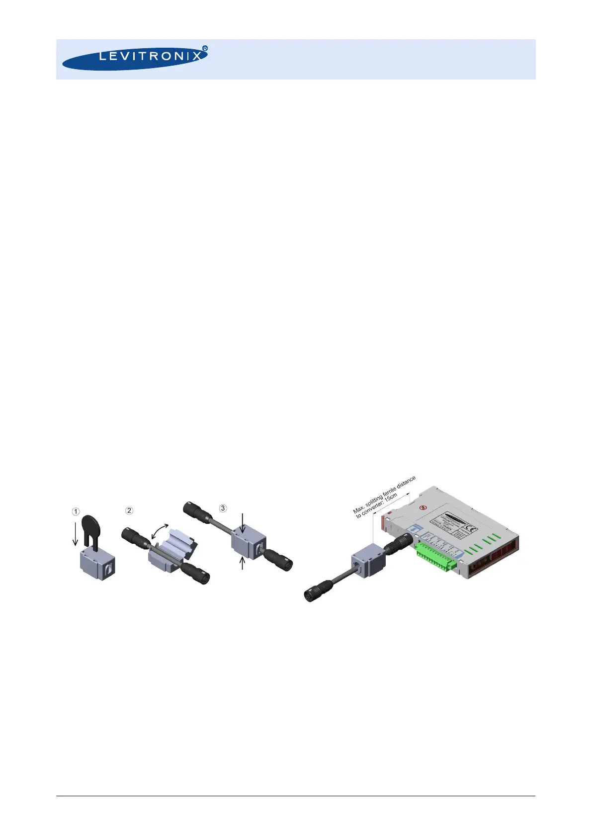
7. To attach the sensor to the converter extension cables according to Table 3 can be used. To
increase robustness against disturbance from other devices or to reduce cross-talking between
multiple flowmeters, the converter comes delivered with an EMI ferrite, which shall be attached to
the sensor cable near to the converter (see Figure 14):
Figure 14: Assembly of EMI ferrite
8. Before powering on check again all wiring connections. Confirm that the terminals are securely
fastened and that there is no possibility of short circuit.