3.2.2 Instructions for Electrical Installation
1. Remove the DC power supply from the converter.
2. Remove the interface connector on the connector box (see Figure 16).
3. Attach the necessary wires (AWG 14-26) according to the pin specifications in Table 9, Table 10 or Table 11.
Strip the sheath approximately 3mm from the wires end. Insert the core into the connector up to the end and
tighten the screw. Confirm that the wires are securely fixed by pulling it by hand.
4. Note: The Field Ground (FG) represents an additional ground potential, which is connected internally to the
signal ports of the converter via varistors. Depending on the specific setup, it might be advantageous from an
EMC perspective to connect the FG to the PE (protective earth). However, in case the FG is connected to PE
the entire grounding concept of the field installation has to be considered in order to avoid stray and
compensating currents triggered by electrical potential differences. If compensating currents between PE and
Ground may occur, the FG should not be connected.
5. For usage of a fuse at the power input slow-blow type with a current rating of the converters (see Table 5) and
25% additional margin is recommended. Consider the inrush current of the converters (see Table 5) during
power start-up, when choosing the fuse type and the AC/DC power supply.
6. Mount the bus connector to the converter and tighten the 2 connector screws.
7. Before powering on, check again all wiring connections. Confirm that the terminals are securely fastened and
that there is no possibility of short circuit.
8. For proper EMI behavior of the LFC-6CIO-PC a ferrite is needed. This can be ordered according to Table 3
and assembled according to Figure 17. All bus wires shall be covered and the ferrite shall be placed at a
distance not longer than 15 cm from the connector box of the converter (see also Figure 10).
Figure 17: Mounting of EMI ferrite for bus wires of LFC-6CIO-PC (See Table 3 for order information)
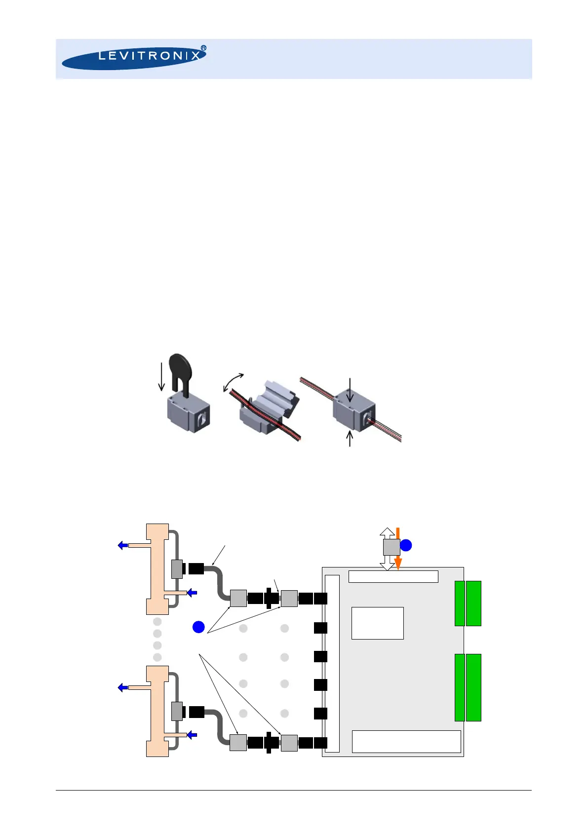
9. If multiple LFC-6CIO-PC are stacked as illustrated in Figure 16, every sensor cable shall be configured with a
ferrite according to Figure 18 (see Table 3 for order information) in order to avoid cross talking of the sensor
signals. The ferrites shall be placed as near as possible to the beginning of the sensor cable (near to the
plastic connector).
Figure 18: EMI ferrites for sensor cables when stacking multiple LFC-6CIO-PC
LEVIFLOW
®
Converter LFC-6CIO-PC
(6-Channel with I/O Signals)
4-Digit Display
Zero Adjustment
Address Setting for RS485
Piezo Transducers In
-/Output
Signal/Power Bus Connector
Power Supply: 24 VDC
RS485 (MODBUS)
- Configuration with PC Software
- Data Reading
Digital
Signal Processor
DSP
Analog Output
Connector
Digital I
/O
Connector
Analog Outputs:
6 Channels
Digital Outputs:
6 Channels
Digital Inputs:
6 Channels
Adaptor/Extension Cable
Wallmountable connector
for cabinet mounting
Interconnect Cable
Various lengths.
Direct connection possible.
Single
-Use Sensor LFS
-xxSU
Single
-Use Sensor LFS
-xxSU
EMI Ferrite for Sensor Cables
For stacking of multiple
converters necessary.
EMI
Ferrite
EMI
Ferrite
EMI
Ferrite
EMI
Ferrite
EMI
Ferrite