4.2.3 Operation with PLC Interface
Table 8 shows the standard configuration of the electrical interface (PLC). For other configurations the
Levitronix
®
Service Software shall be used (see reference on title page of this manual).
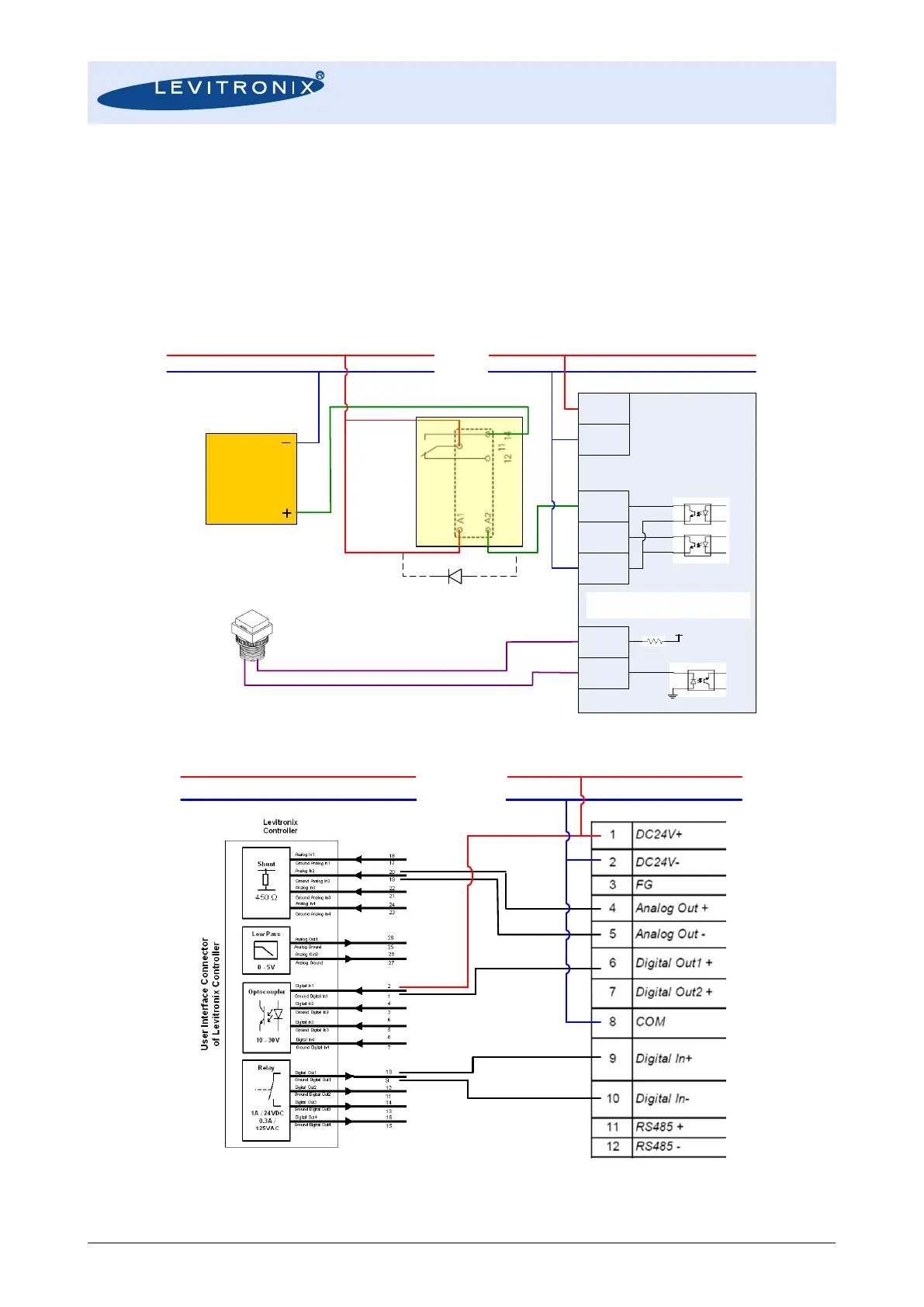
Figure 21 shows an example how to connect the flow converter to a relays to control a shutoff valve by a digital
output. Note that if a protective diode is not integrated in the relay, it must be connected additionally as shown
in Figure 21. This setup additionally shows how to connect a push-button to digital input (e.g. for reset of
volume counter, which shall be configured with Levitronix
®
Service Software). Figure 22 shows an example
how to connect the PLC of the converter to a Levitronix
®
pump system.
Figure 21: Controlling a shutoff valve by digital output of converter
Figure 22: Usage of PLC of flow converter with a Levitronix
®
pump system