User Manual for LEVIFLOW
®
LFS-SU Flowmeters
www.levitronix.com
PL-4509-00, Rev09, DCO# 21-230
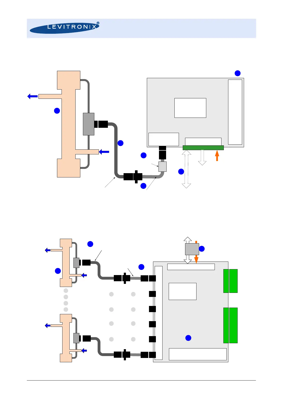
2.2 Standard System Configurations
2.2.1 Single Channel System Configuration with LFC-1C-PC
Figure 4: Standard flowmeter system configuration
2.2.2 Multi-Channel Configuration with LFC-6CIO-PC
Figure 5: Standard flowmeter configuration with LFC-6CIO-PC converter
Single-Channel Converter LFC-1C-PC
4-Digit Display
Zero Adjustment
Adress Setting for RS485
Piezo Transducers
In-/Output
Electrical Interface
Power Supply: 24 VDC
Analog and
Digital Outputs
- 1x Analog Output
- 2x Digital Outputs
- 1x Digital Input
Digital
Signal Processor
DSP
Adaptor/Extension Cable
Wallmountable connector
for cabinet mounting
Interconnect Cable
Various lengths.
Direct connection possible.
RS485 (MODBUS)
- Configuration with PC Software
- Data Logging
- Fieldbus Array of Multiple Sensors
LEVIFLOW
®
Single-Use Sensor LFS-xxSU
Flow Out
Flow In
Connector
Box
EMI Ferrite
LEVIFLOW
®
Converter LFC-6CIO-PC
(6-Channel with I/O Signals)
4-Digit Display
Zero Adjustment
Address Setting for RS485
Piezo Transducers In
-/Output
Signal/Power Bus Connector
Power Supply: 24 VDC
RS485 (MODBUS)
- Configuration with PC Software
- Data Reading
Digital
Signal Processor
DSP
Analog Output
Connector
Digital I
/O
Connector
Analog Outputs:
6 Channels
Digital Outputs:
6 Channels
Digital Inputs:
6 Channels
EMI
Ferrite
Adaptor/Extension Cable
Wallmountable connector
for cabinet mounting
Interconnect Cable
Various lengths.
Direct connection possible.
Single
-Use Sensor LFS
-xxSU
Single
-Use Sensor LFS
-xxSU