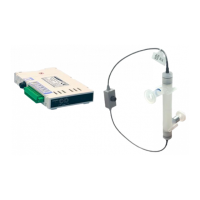
User Manual for LEVIFLOW
®
LFS-SU Flowmeters
www.levitronix.com
PL-4509-00, Rev09, DCO# 21-230
5 Inspection and Maintenance
The LEVIFLOW
®
ultrasonic flowmeters do not require special maintenance since there are no moving parts
that can be subjected to wear and tear. However, the following periodical checks are recommended to ensure
smooth and reliable operation:
1. Check for excessive mechanical stress onto the flow sensor body for example caused by bended piping.
2. Inspect for loosen connections caused by excessive pipe vibrations.
3. Inspect the sensor visually for any deposits, excessive bubbles or foreign materials in the measuring tube.
6 Troubleshooting
6.1 Common Troubles
“0-Er” indication on converter display
Zero adjustment is not working
properly.
Check if the circuit is filled with liquid and the flow is actually
zero, and conduct zero adjustment again
“b-Er” indication on converter display
Incorrect signal received from
measurement in the sensor.
- Check if measuring tube is filled with liquid
- Check if there is something in the measuring path
disturbing the ultrasonic wave (bubbles, solid substances
etc)
- Check if excessive noise is generated in the neighborhood
of the sensor (heavy devices like motors, high voltage
cables etc)
- Check if the cables are connected correctly and not
damaged
“c-Er” indication on converter display
Parameter communication to
sensor is not working properly
or corrupt data on sensor.
- Check if sensor is connected.
- Check sensor cabling and connection.
- Disconnect and reconnect sensor.
“SHrT” indicat. on converter display
Short-circuit on flow sensor
transducer.
- Check sensor cabling and connection for damage.
- Disconnect and reconnect sensor.
- If issue is still not solved, replace sensor cable.
Zero flow is indicated even if there is
flow in the hydraulic circuit
Wrong parameter and
mechanical setup of sensor or
zero adjustment performed
under flow conditions.
- Check if the parameters have been set to the optimal
values
- Check if the flow direction is correct
- Redo zeroing at 0 lpm
Zero flow is indicated at flow level
below cut-off value.
Standard cut-off value as
shown in Table 6 is not
adequate for application.
- Adapt lower cut-off value with Levitronix
®
Service Software
The flow indication does not match
the real flow
Wrong parameter settings,
excessive bubbles or solids in
the measurement path.
- Check if the parameters in the converter are set correctly
- Inspect the flow path for stagnating solids
- Inspect the measurement path for excessive bubbles
Above full scale flow is indicated or
the flow signal is unstable
Wrong parameter settings,
excessive bubbles or solids in
the measurement path.
- Check if the parameters in the converter are set correctly
- Inspect the flow path for stagnating solids
- Inspect the measurement path for excessive bubbles
Spikes on flow measurement
Influence from other devices.
- Use the standard EMI ferrites on the sensor cables.
Table 14: Potential troubles and the possible countermeasures
6.2 Troubleshooting with Levitronix
®
Service Software
More detailed error analysis can be done with the Levitronix
®
Service Software. Contact Levitronix
®
for a
sample of the configuration software and the according manual (see reference on title page of this manual).

 Loading...