3.3.3 Instructions for Mechanical and Hydraulic Installation
1. For mounting and exchanging the sensors and assure proper operation it is recommended to use the LMK-x.2 mounting
brackets, which can be ordered according to Table 3 and are shown in Figure 2. Contact Levitronix
®
for detailed drawing
specifications.
2. Alternativally, the sensor body can be mounted with the fixation holes as shown in Figure 7 and Figure 8. Assure that the
fixation of the flow sensor and that the weight of the inlet and outlet circuit on the fittings are not causing excessive forces
resulting in bending the flow measurement path, which might influence the flow measurement.
3. Assure that at the mounting location the allowed ambient temperature and humidity ranges are not exceeded:
➔ Temperature range: 0 – 60 °C (32 – 140 °F)
➔ Humidity range: 30 - 85% R.H. (no condensation)
4. The flow circuit should be filled completely with fluid. The converter DSP (Digital Signal Processor) contains special
algorithms, which increase the robustness of the measurement against bubbles. However, assure that excessive bubbles
are avoided in the circuit.
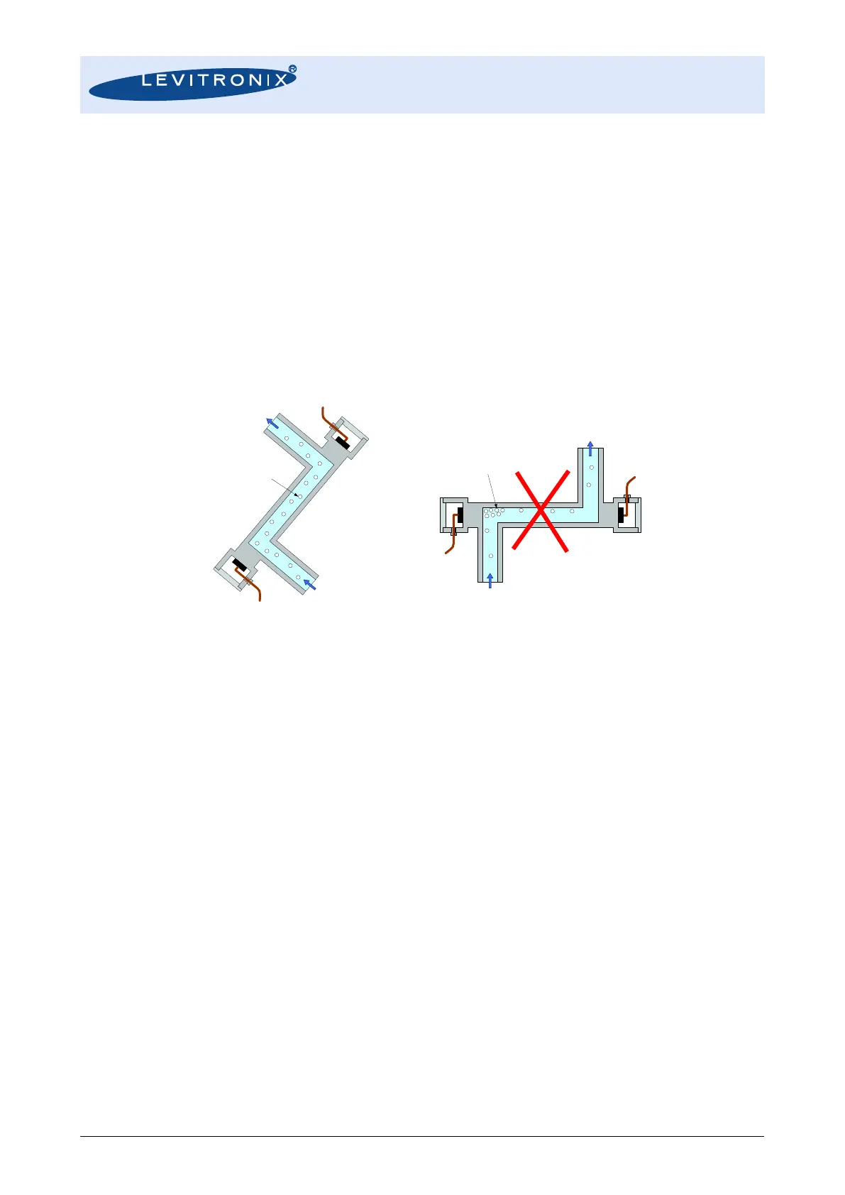
5. Ideal mounting position for the flow sensor is 45
0
(see Figure 20) with upward flow direction to avoid the stagnation of
bubbles and particles in the measuring tube.
Figure 20: Mounting position of sensor
6. An arrow mark on the flow sensor indicates the flow direction. Make sure that the arrow corresponds to the direction of
the flow in the hydraulic circuit.
7. Avoid excessive vibrations such as in the neighborhood of displacement pumps. Insufficient contact of the transducer
(within the sensor) onto the pipe wall caused by vibration may result in inaccurate measurement.
8. The flowmeter measures flow velocity. In order to obtain fully developed flow pattern for accurate velocity measurement,
straight run of 10x sensor ID upstream and of 5x ID downstream is recommended (see Figure 7 and Figure 8 for ID
specifications of the sensor models). If non-uniform turbulent flow or swirl flow is expected, install longer upstream straight
run and/or a flow-rectifier.
9. To install on pipe that has open end, the sensor should be mounted in lower position of the pipe line.
10. The sensor should be mounted where pressure in the pipe is above the atmospheric pressure.
11. Devices like valves are recommended to be installed downstream of the sensor in order to prevent formation of bubbles
in the liquid. An upstream valve may form bubbles reducing the intensity of the ultrasound signal and interfering with
measurement.
12. A bypass pipe run (including bypass valve and shutoff valve) is recommended for easy zero adjustment and maintenance.
13. Please confirm that the maximum pressure is below the specification defined in Table 7.
14. After setup a “Zeroing” is recommended. Assure that the sensor is filled completely with the according fluid and is free of
bubbles. Stable liquid properties should be assured by flushing the circuit with the final liquid until temperature and
viscosity becomes stable. After this, zero flow shall be realized. Then push the “ZERO ADJ” button on the converters for
about 3 seconds. During adjustment “0ADJ” appears on the converter display.
15. If Re-Zeroing is regularly necessary, automation is possible over the digital input of the converter.
16. In the following cases a re-zero is recommended:
a. 30 minutes after power-on of a cool converter and sensor
b. Change of fluid properties (temperature, viscosity, density)
c. Change of chemistry
d. Change of the hydraulic circuit