Lexicon
7-5
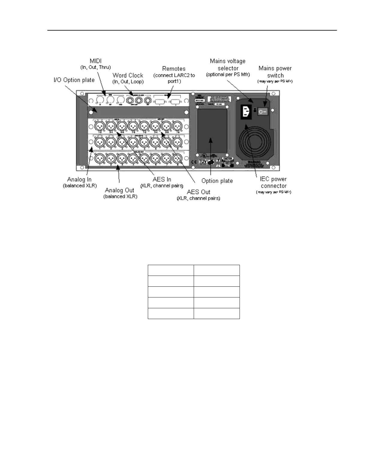
Figure 1-1 960L Rear Panel
The IO Backplane supports five, uniquely addressable card slots, which are accessed from the rear of the
960L chassis (Fig 1-1). With the exception of the slot address decodes, the interface signals to each slot is
identical. However, because of mechanical and specific electrical constraints, not all cards can or should be
randomly located. The recommended slot ordering is:
Slot 1(top) IO Clock PCB
Slot 2 Spare Slot
Slot 3 AES PCB
Slot 4 AIN PCB
Slot 5(bottom) AOUT PCB
Table 1-1 Recommended Rear Panel Slot Ordering
The most critically placed PCB is the IO Clock card. This card supplies the master bit (TMIX_CKI) and word
clock (TMIX_WCKI) for the entire system and needs to be located in the topmost slot to drive one end of
the TMIX_CKI transmission line. (Note: 256FS, 128FS, 64FS, and FS clocks are also available but are not
currently used by any IO card.)
Circuit Description
This section is a page by page description of the 960L IO Backplane card schematic.
Sheet 1
NLX to IO Backplane Connectors (Sheet 1)
The NLX backplane and the IO backplanes are connected by two 40-pin ribbon cables which connect to
J10 and J11. This interface is comprised of an 8-bit, non-multiplexed address and data system control bus
 Loading...


