Lexicon
7-41
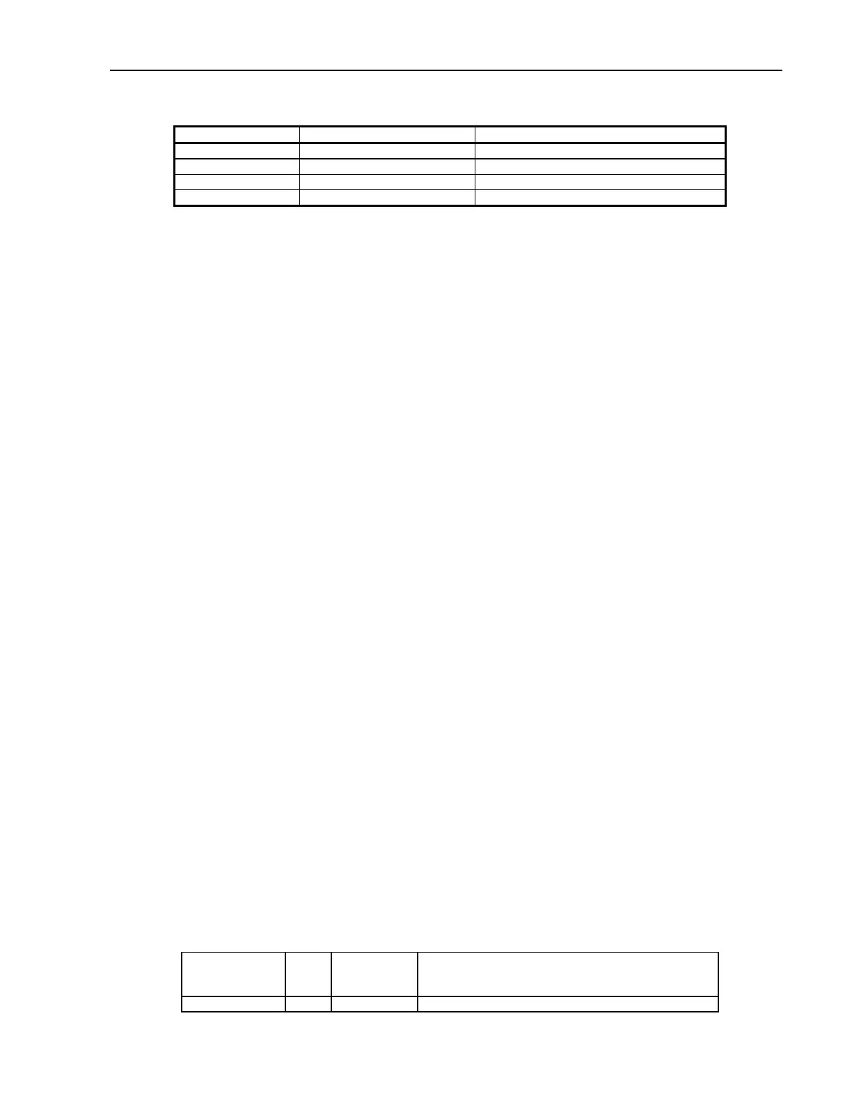
Base Address SA-1100 LARC2
0x1800 0000 Static Bank Select 3 Configuration Register
0x1000 0000 Static Bank Select 2 LARC2 Registers
0x0800 0000 Static Bank Select 1 8 Mb Flash
0x0000 0000 Static Bank Select 0 Boot ROM
Table 2-1 LARC2 Memory Map
The bottom partition (0x0000 0000 to 0x3FFF FFFF) is dedicated to static memory devices (ROM, Flash,
SRAM) and to the PCMCIA expansion bus area. This space is divided into four 128 M byte blocks for static
memory devices and two 256 Mbyte blocks for PCMCIA.
The next partition (0x4000 0000 to 0x7FFF FFFF) is reserved. Accessing this reserved space results in a
data abort exception.
The third partition (0x8000 0000 to 0xBFFF FFFF) contains all on-chip registers. This block is further
subdivided into four blocks of 256 M-bytes each. They contain the control registers for the major functional
blocks within the chip. The LCD and DMA controllers occupy the top 256 M-byte partition.
The fourth partition (0xC000 0000 to 0xFFFF FFFF) contains DRAM memory. The bank sizes for DRAM
are fixed at 128 Mbyte each. The next 256 Mbyte block in this partition is mapped within the memory
controller and returns zeros when read. This function is intended to facilitate rapid cache flushing by not
requiring an external memory access to load data into the cache. Writes to this space have no effect. The
top 384 M-byte of this partition is reserved. Accessing this space causes a data abort exception.
Reset Controller (U5, sheet 1.)
When power is applied, U5 (DS1233) asserts RESET/ and monitors the rise of the 3.3V logic supply. Once
it rises above 2.97V (within 10% of 3.3 V), RESET/ remains asserted for an additional 350msec, allowing
circuitry to stabilize at nominal operating voltage in the reset state.
When the RESET/ signal is asserted low, SA-1100 stops executing instructions, asserts the RESET_OUT/
pin, and then performs idle cycles on the bus.
When the RESET/ is negated, SA-1100 does the following:
1. Forces the internal program counter to fetch the next instruction from address 0h0000 0000.
2. Based on the state of ROM_SEL pin, fetches the instruction from either 16-bit (ROM_SEL low) or 32-bit
space (ROM_SEL high).
Main Memory (sheet 2)
DRAM (U11, U17, sheet 2)
LARC2 uses two 64 Mbyte, 60 ns EDO DRAM chips organized as 1 bank x 4 M Words x 32 bits giving the
system 16 MBytes of DRAM. The memory occupies address space 0xC000 0000 to 0xC0FF FFFF. The
following table lists the memory transactions that are supported.
Bus Operation Burst
Size
Starting
Address
Bits [4:2]
Description
Read single 1 Any Generated by core, DMA or read buffer request.
 Loading...


