Lexicon
7-11
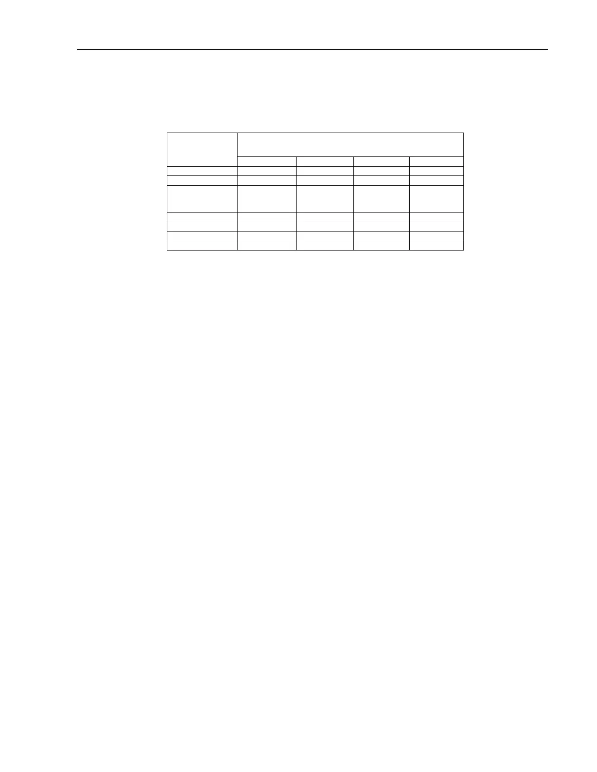
All system clocks are derived from the PLL_512FS clock signal. The frequency of PLL_512FS is 512 times
the rate fo TMIX_WCKI. The table below lists the rates of each system clock as a function of the system
sample rate.
Sample Rate
Signal
44.1 Khz 48 Khz 88.1 Khz 96 Khz
PLL_512FS
22.5792 Mhz 24.576 MHz 22.5792 Mhz 24.576 MHz
TMIX_CKI
22.5792 Mhz 24.576 MHz 22.5792 Mhz 24.576 MHz
TMIX_WCKI
44.1 Khz
48 Khz
44.1 Khz 48 Khz
B_256FS 11.2896 Mhz 12.288 Mhz 22.5792 Mhz 24.576 MHz
B_64FS/ 2.8224 Mhz 3.072 Mhz 5.6384 Mhz 6.144 Mhz
B_FS/ 44.1 Khz 48 Khz 88.1 Khz 96 Khz
BNC_WCOUT 44.1 Khz 48 Khz 88.1 Khz 96 Khz
The external BNC wordclock can be used to derive system clocking. The 960L system software can first
preview the incoming BNC wordclock by assigning it to the IO backplane SLOT_PCLK_INT/ signal. Once
satified, the 960L system software can select the BNC word clock as the source for system clocking. Clock
selection and preview clock enable are controlled by the control register, CTLREG in the U1 FPGA.
Clock Selection
Clocks can be derived from both on- and off-board frequency references.
The on-board references are two high-accuracy (10ppm) crystal oscillator modules U3 (24.576MHz) and U4
(22.5792MHz), that are connected to inputs of U2. These crystal frequencies are multiples of the standard
48/96kHz and 44.1/88.2kHz sampling rates, respectively.
Off-board references are sample-rate wordclocks that come either from the on-board BNC receiver circuitry
described above, or from pin C5 of the I/O backplane. Other I/O modules can supply this wordclock via the
backplane, so that a variety of external sources can provide the reference clock for the system, according to
the specific type of I/O interface module.
PLL Support
Logic within U2 that is involved with the operation of the PLL is described below.
Phase-Locked Loop
All clocks that are distributed to the digital audio systems in the 960L ultimately derive from the oscillator in
the on-board PLL (sheet 3). The PLL consists of a Voltage-Controlled Oscillator (VCO, U10, MC12148), a
Phase/Frequency Detector (PFD) implemented within CPLD U2, and an active filter formed by op-amp U6
and associated circuitry. The VCO oscillates around the 22-24MHz range, depending on sample rate. The
PFD and other logic within U2 lock the oscillator appropriately to whatever source is chosen to be the
frequency reference. Reference sources affect the system only indirectly, when they become the reference
for the PLL. Logic within U2 divides the VCO frequency to form the several system clocks that are
distributed to the backplane. This clock tree, along with the action of the VCO, ensures continuous coherent
clocking within the system.
The PFD operates at the single-speed wordclock rate in both single- and double-speed modes, i.e 48kHz at
both 48 and 96kHz. The VCO frequency is always divided by 512 to form one input to the PFD. The other
PFD input is derived from the chosen reference source, conditioned by other logic within U2 to be at the
single-speed wordclock rate.
For internal crystal operation, a multiplexer within U2 selects the input from one crystal and divides it by 512
to become 48kHz or 44.1kHz, for U3 or U4, respectively. External wordclock sources (BNC, e.g.) get
 Loading...


