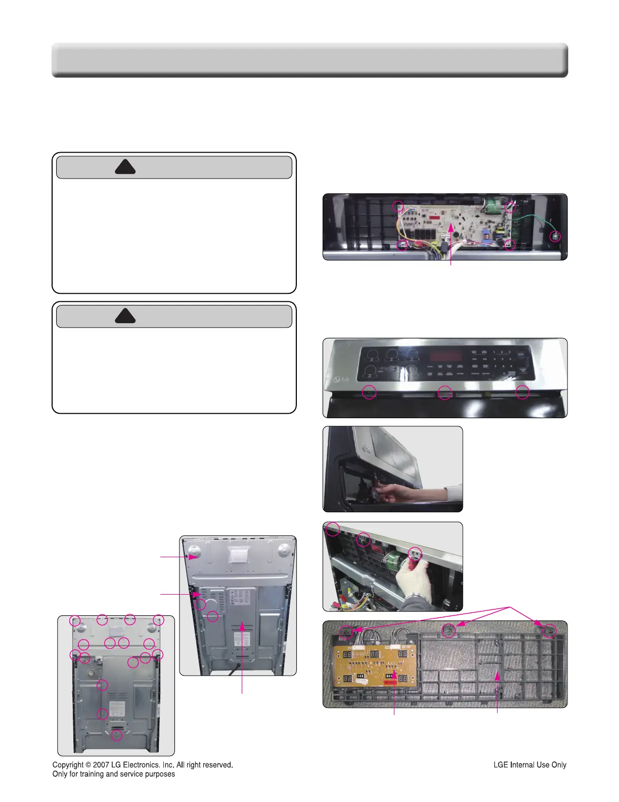
6. Remove the 5 screws and wirings from Main
PCB and Main PCB can be detached from the
support assembly.
7. Remove the 3 screws from controller's lower side
and pull the support assembly out of the
controller by using the same method such as
below pictures.
Pull 3 hooks out of
the controller and the
PCB support can be
detached easily.
8. Remove 4 screws from Cooktop Display PCB
and the PCB can be detached from the support.
3-2
COMPONENT ACCESS
1. Turn off the electrical supply going to the range.
2. Pull the range away from the wall so that you can
access the rear panel.
3. Remove 2 screws from the lamp cover and
remove the lamp cover.
4. Remove 12 screws from the controller cover and
remove the controller cover.
5. Remove the 4 screws from the back cover and
remove the back cover
REMOVING THE LAMP
REMOVING THE LAMP
, CONTROLLER, BACK COVER AND
, CONTROLLER, BACK COVER AND
CONTROLLER ASSEMBL
CONTROLLER ASSEMBL
Y(MEMBRANE, PCB, SUPPOR
Y(MEMBRANE, PCB, SUPPOR
T)
T)
WARNING
• DISCONNECT power supply cord
from the outlet before servicing.
• Replace all panels and parts before
operating.
• RECONNECT all grounding devices.
- Failure to do so can result in severe personal
injury, death or electrical shock.
CAUTION
• Be careful when you work on the
electric range handling the sheet
metal part.
- Sharp edge may be present and you can cut
yourself.
Control Cover
Lamp Cover
Back Cover
Main PCB
3 hooks
Cooktop Display PCB
PCB support
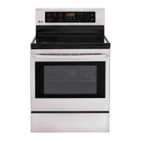
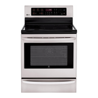
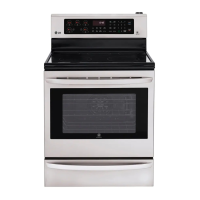
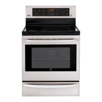
For Model : LRE3085ST /00
 Loading...