7400 Series UPS User Manual Chapter 1 - General Description
Single Module and One plus One Systems Introduction
1-3
Issue 2
(02/98)
12 Pulse Rectifier
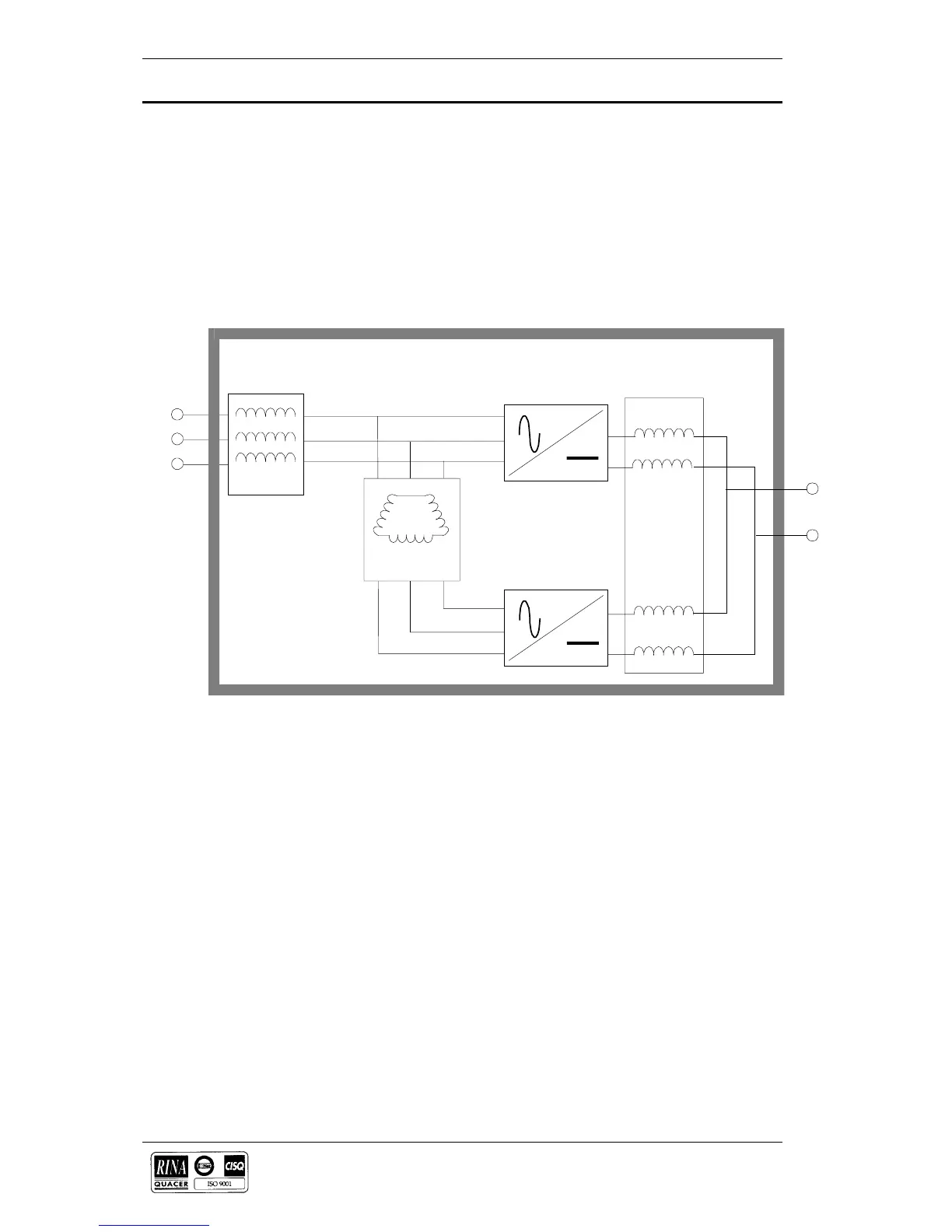
The UPS basically operates as an a.c.-d.c.-a.c. converter (see figure 1-1).
The first conversion stage (from a.c. to d.c.) uses a 3 phase 12 pulse (2 x
6 pulse), fully-controlled SCR bridge rectifier system to convert the
incoming mains supply into a regulated d.c. busbar (432V d.c. for a
380V a.c. input; 446V d.c. for a 400V a.c. input or 459V d.c. for a 415V
a.c. input).
The input a.c. supply is applied (a) directly into a six pulse rectifier and
(b) via a 30° phase shift transformer into a second six pulse rectifier (see
figure 1-2). This phase shifting results in less distortion of the alternating
input supply (i.e. the lower order harmonics are cancelled).
Inverter
The d.c. busbar produced by the rectifier provides both battery charging
power and power to the inverter section-which uses the latest IGBT
switched pulse width modulation (PWM) design and provides the second
conversion phase; i.e. reconverting the d.c. busbar voltage back into an
a.c. voltage waveform.
During normal operation both the rectifier and inverter sections are
active and provide regulated load power whilst simultaneously float
charging the battery. In the event of a mains power failure, the rectifier
becomes inoperative and the inverter is powered solely from the battery.
Critical load power is maintained under these conditions until the battery
is fully discharged, whereupon the UPS shuts down. The end of battery
discharge is assumed when the battery voltage falls to 320 Vd.c. for a
system with a 380V a.c. input supply, 330V d.c. with a 400V a.c. input
supply and 340V d.c. with a 415V a.c. input supply.
The period for which the load can be maintained following a mains
power failure is known as the system’s ‘Autonomy Time’ and is
dependent upon both the battery A/Hr capacity and the applied
percentage load. It is usual in larger installations to provide an
alternative UPS input power source from a standby generator when the
L1
L2
AT1
Mains
Supply
12 Pulse
(2 x 6 pulse)
Rectifier system
To DC
Busbar
DC
Inductor
Phase
displacement
transformer
Inductor
Rectifier
bridges
Rectifier
bridges
Figure 1-2 . 12 Pulse rectifier block diagram
 Loading...