Chapter 1- General Description 7400 Series UPS User Manual
Design Concept Single Module and One plus One Systems
6310018a.02.doc
1-6
Issue 2
(02/98)
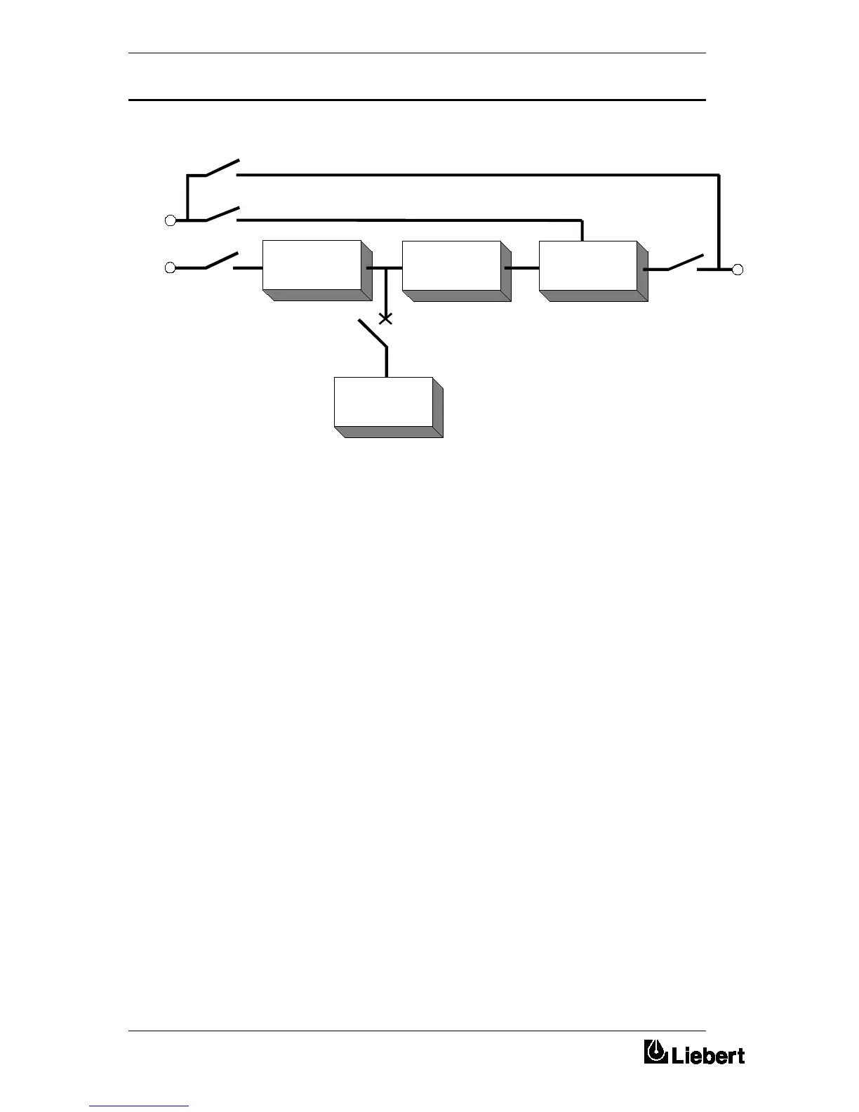
Figure 1-1 . Series 7400 UPS isolator configuration
The battery is connected to the d.c. Busbar through a circuit breaker
fitted inside the battery cabinet or located adjacent to the batteries where
a battery cabinet is not used. This circuit breaker is closed manually, but
it contains an undervoltage release coil which enables it to be tripped
from the UPS control electronics following certain detected faults. It also
has a magnetic trip facility for overload protection.
In the case of the 80kVA and 120kVA UPS models, the batteries
associated with the UPS are generally housed in a purpose-built cabinet
located along-side the main UPS equipment.
It is possible to install batteries of various types and capacity in the
cabinet to obtain the required autonomy characteristics.
The battery cabinet can be purchased in one of the following forms:
1. Complete installation comprising the battery cabinet, batteries and
circuit breaker.
2. Battery cabinet and circuit breaker only with no batteries.
3. Battery cabinet only with no batteries or circuit breaker.
For the larger units and as an alternative to the battery cabinets, a
battery circuit breaker can be provided in a custom built box. This
Battery Circuit Breaker Box is designed to be wall or rack mounted and
is connected between the UPS and Battery.
Mains
Supply
RECTIFIER
STATIC
SWITCH
BATTERY
INVERTER
UPS
Output
Supply
Bypass
Supply
Battery
Circuit
Breaker
Input
Isolator
Output
Isolator
Bypass Isolator
Maintenanc
 Loading...