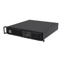
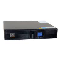
7400 Series UPS User Manual Chapter 4 - Optional equipment
Single Module and One plus One Systems Remote Alarm and Control Panel (Part No. 4305002 A)
6310018a.02.doc
4-11
Issue 2
(02/98) LCA 10/01
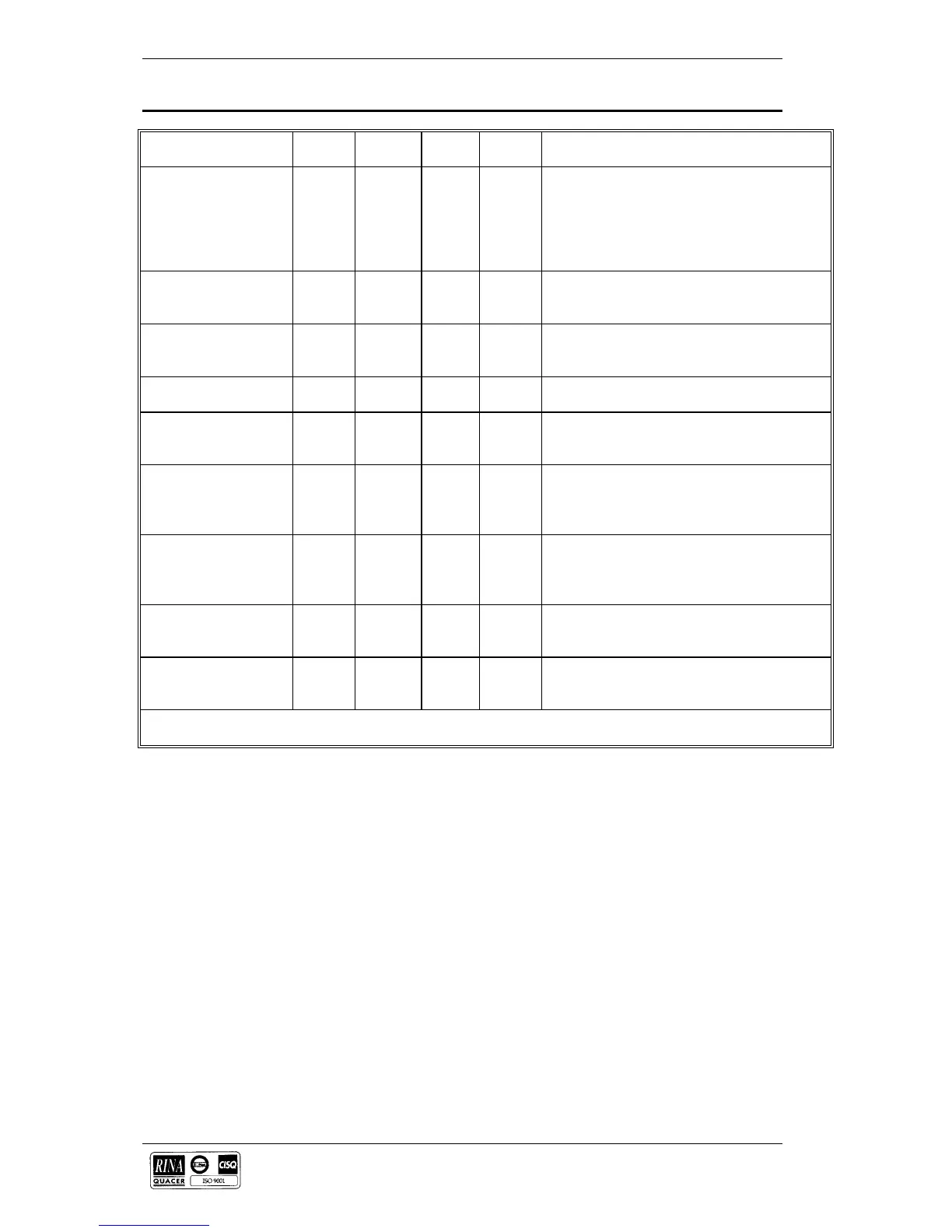
Panel Indication Priority Ident
Fig. 4-5
Colour Normal
State
Interpretation
UPS Module status status 6 red/
green
ON
green
These are bi-coloured indicators, when lit green
indicate that the UPS is OK, and when lit red
indicate that a fault is present. Indication for
number 1 module is on the left and number 2
module next to it, the other four indicators are
not used for this application.
Mains OK status 21 green ON When lit indicates that the mains supply to the
modules is OK and therefore bypass supplies
are available.
Load on Mains status 19 green OFF When lit indicates that the load has transferred
to the bypass supplies and is therefore
unprotected.
UPS OK status 20 green ON When lit indicates that the UPS inverters are
synchronised and UPS supplies are available.
Load on UPS status 18 green ON When lit this indicates that the load is being
supplied by the UPS inverters - the normal
status.
UPS OFF status 17 red OFF This shows that the UPS OFF switch, on the
remote panel has been operated and the
inverters have been shut down, the load will be
supplied via the bypass if available.
UPS OFF switch 16 OFF This switch selects all the UPS inverters OFF.
It can only be used when enabled by the key
enable switch (4). The UPS OFF indication
(17) accompanies its operation.
Alarm silence switch 7 OFF This switch silences the horn on the Remote
Alarm and Control panel only, it has no effect
on the UPS system or any indications.
UPS OFF enable switch 4 OFF This key operated switch enables the UPS OFF
switch and is security against the UPS OFF
switch being operated accidentally.
Table 4-2
Power Supply
The panel contains a single phase 220-240 Vac mains driven power
supply. Power is applied through a standard three pin mains connector
located at the top of the panel (plug provided) - use 3 core 0.5mm cable
minimum.
Alarm connections
Alarm connections from the UPS modules are provided by connectors
M1 (5 way terminal block), M2 (15 way terminal block) and M3 (15 way
terminal block) on the Output Interface boards (4590044E), to CN1 (50
pin D-type connector) on the Remote Alarm and Control panel (4305002
A).
Full installation instructions are provided with the option kit.
4.5.2 Connections
 Loading...