7400 Series UPS User Manual Chapter 1 - General Description
Single Module and One plus One Systems Operator Control Panel
6310018a.02.doc
1-13
Issue 2
(02/98)
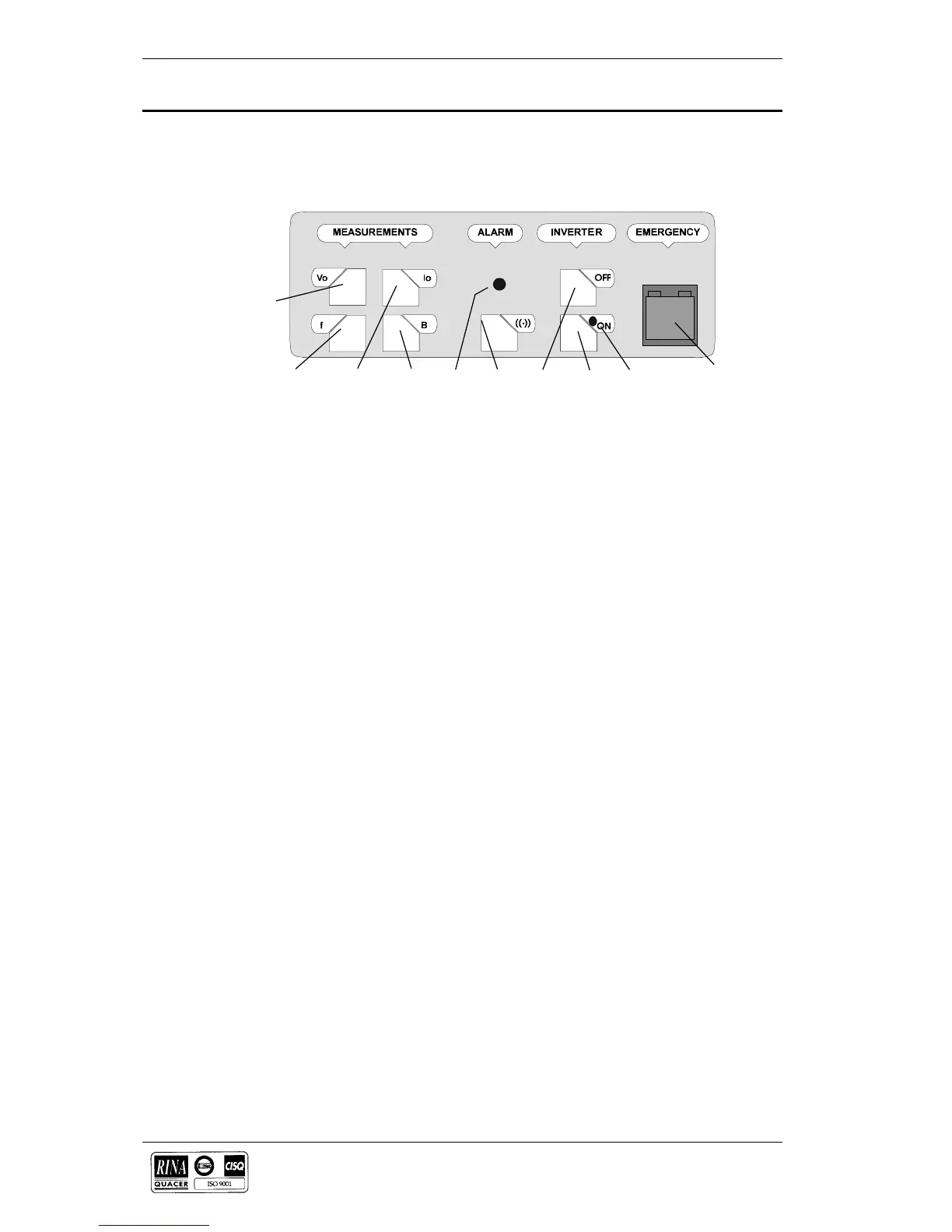
Seven tactile switches are located on the Operator Panel, together with
an emergency stop pushbutton which is fitted with a safety cover to
prevent inadvertent operation.
Switch S1 (Vo) - Output volts:
When this switch is pressed, the lower line of the LCD Display shows
the output line-to-line voltages on all three phases.
Switch S2 (Fo) - Output frequency:
When this switch is pressed, the lower line of the LCD Display shows
the output frequency.
Switch S3 (Io) - Output current:
When this switch is pressed, the lower line of the LCD Display shows
the output line (and neutral) currents.
Switch S4 (B) - Battery:
When this switch is pressed, the lower line of the LCD Display shows
the battery voltage, current and % charge or autonomy time remaining in
minutes. Note that a discharging current is symbolised by a preceding
minus [] sign.
Switch S5 - ((.)) - Alarm reset:
Pressing this switch cancels the audible alarm. The alarm led and
messages will remain active if a detected fault condition is still present.
Switch S6 - Inverter OFF:
Pressing this switch turns OFF the inverter and causes the load to be
transferred to the static bypass supply.
Switch S7 - Inverter ON:
Pressing this switch activates the inverter and causes the load to be
transferred to the inverter side of the static switch after the inverter
voltage has had time to stabilise.
Switch S8 - Emergency stop:
When the emergency stop switch is pressed it disables the static switch
block entirely (so removing load power). It also disables the rectifier and
inverter, and trips the battery circuit breaker. Under normal
circumstances it does not remove UPS input power since this is applied
through a manually controlled isolator; however, if the UPS input supply
is connected via a circuit breaker having an electrical trip facility the
emergency stop signal can be used to drive the external circuit breaker’s
trip circuit.
There are two leds contained within the switch panel area:
LS7 - Alarm:
This led accompanies the audible alarm warning when any alarm
condition is initiated. The audible warning can be cancelled by the reset
switch (S5) but LS7 will only extinguish after the alarmed condition has
reverted to normal.
1.4.2 Control switches
S1
S2 S3 S4 LS7 S5 S6 S7 LS8
S8
Figure 1-1 . Control panel switches
 Loading...